
Nissan Rogue Service Manual: Radiator
Exploded View
REMOVAL
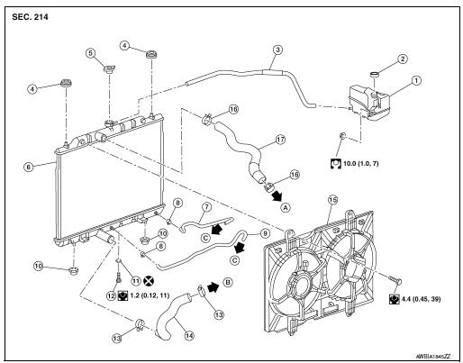
- Reservoir tank
- Reservoir tank cap
- Reservoir tank hose
- Mounting rubber (upper)
- Radiator cap
- Radiator
- CVT fluid cooler hose
- Clamp
- CVT fluid cooler hose
- Mounting rubber (lower)
- O-ring
- Drain plug
- Clamp
- Radiator hose (lower)
- Cooling fan assembly
- Clamp
- Radiator hose (upper)
- To water outlet
- To water inlet
- To CVT fluid warmer
Removal and Installation
REMOVAL
WARNING: Do not remove the radiator cap when the engine is hot. Serious burns could occur from high-pressure engine coolant escaping from the radiator. Wrap a thick cloth around the cap. Slowly push down and turn it a quarter turn to allow built-up pressure to escape. Carefully remove the cap by pushing it down and turning it all the way.
NOTE: When removing components such as hoses, tubes/lines, etc., cap or plug openings to prevent fluid from spilling.
- Disconnect battery negative terminal.
- Disconnect battery positive terminal. Refer to PG-77, "Exploded View".
- Depower SRS system. Refer to SR-2, "Service".
- Drain engine coolant from radiator. Refer to CO-8, "Draining".
CAUTION:
- Perform this step when the engine is cold.
- Do not spill engine coolant on the drive belt.
- Remove engine under cover. Refer to EXT-37, "ENGINE UNDER COVER : Removal and Installation".
- Remove over fender. Refer to EXT-30, "FRONT OVER FENDER : Removal and Installation".
- Remove front air spoiler. Refer to EXT-16, "Exploded View".
- Remove fender protector side cover. Refer to EXT-28, "FENDER PROTECTOR : Exploded View".
- Remove radiator core support (upper). Refer to EXT-16, "Exploded View".
- Remove radiator hose (upper/lower) from radiator. Refer to CO-13,
"Exploded View".
CAUTION: Do not spill engine coolant on the drive belt.
- Remove clamps from radiator hose (upper/lower), (if necessary).
NOTE: Radiator hoses have glued on clamps.
- Apply heat gun at glued location, usually located on the underside of the radiator hose (upper/lower), a short distance from clamp.
- While applying heat, simultaneously wiggle or pressure the clamp tab gently until it can be removed from the hose without damaging it.
WARNING: Wear hand protection while applying heat to remove glue.
- Remove condenser. Refer to HA-37, "CONDENSER : Removal and
Installation".
CAUTION: Be careful not to damage the condenser.
- Remove cooling fan assembly. Refer to CO-17, "Exploded View".
CAUTION: Be careful not to damage the radiator.
- Remove radiator.
CAUTION: Be careful not to damage or scratch the radiator.
INSTALLATION
Installation is in the reverse order of removal.
- After installation, refill coolant and check for leaks. Refer to CO-9, "Refilling" and CO-8, "Inspection".
CAUTION: Do not spill coolant in engine compartment. Use a shop cloth to absorb coolant.
Radiator hose
NOTE:
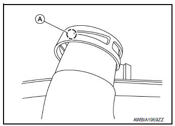
- Once hose clamp has been placed into position, place a small amount of glue between the hose and the clamp (A).
- Insert the radiator hose (1) all the way to the stopper (2) or by 33 mm (1.30 in) (hose without a stopper).
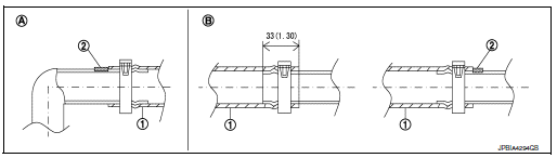
Unit: mm (in)
- Radiator side
- Engine side
- For the orientation of the hose clamp pawl, refer to the figure.
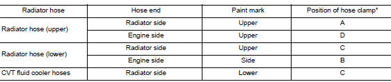
*: Refer to the illustrations for the specific position each hose clamp tab.
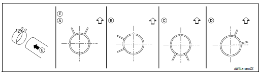
E. View E
 : Vehicle upper
 : Vehicle back side
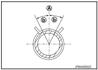
- The angle (b) created by the hose clamp pawl and the specified line (A) must be within ±30 as shown in the figure.
- To install hose clamps (1), check that the dimension (A) from the end of the hose clamp on the radiator hose to the hose clamp is within the reference value.
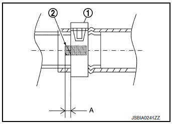
Dimension “Aâ€� : (-3) – (+3) mm [(-0.12) − (+0.12) in]
Inspection
INSPECTION AFTER INSTALLATION
- Start and warm up the engine. Check visually and verify that there are no engine coolant leaks, if engine coolant leaks are found perform inspection. Refer to CO-8, "Inspection".

 Cooling fan
Exploded View
Fan shroud
Fan motor (LH)
Fan motor (RH)
Cooling fan (RH)
Cooling fan (LH)
Front
Removal and Installation
REMOVAL
WARNING:
Do not remove the radia ...
Other materials:
P0705 transmission range sensor A
DTC Description
DTC DETECTION LOGIC
DTC
CONSULT screen terms
(Trouble diagnosis content)
DTC detection condition
P0705
T/M RANGE SENSOR A
[Transmission Range Sensor A Circuit (PRNDL
Input)]
When all of the following conditions are satisfied and this state is
...
Oil pan
Exploded View
COMPONENT PARTS LOCATION
Transaxle assembly
Oil pan gasket
Oil pan
Drain plug
Drain plug gasket
Magnet
Overflow plug
O-ring
Always replace after every
disassembly.
: N·m (kg-m, ft-lb)
: N·m (kg-m, in-lb)
: Apply CVT fluid
Removal and Installation ...
Instrument brightness control
Instrument brightness control
Push the “-� button A to decrease the brightness
of instrument panel lights when driving at
night.
Push the “+� button B to increase the brightness
of instrument panel lights when driving at
night.
Turn signal switch
Turn signal
Move ...
