Nissan Rogue Service Manual: Oil pan
Exploded View
COMPONENT PARTS LOCATION
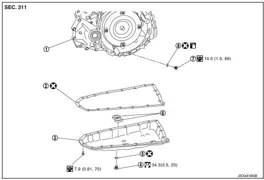
- Transaxle assembly
- Oil pan gasket
- Oil pan
- Drain plug
- Drain plug gasket
- Magnet
- Overflow plug
- O-ring
 Always replace after every
disassembly.
Always replace after every
disassembly.
 : N·m (kg-m, ft-lb)
 : N·m (kg-m, in-lb)
 : Apply CVT fluid
Removal and Installation
REMOVAL
- Remove engine under cover. Refer to TM-205, "Removal and Installation".
- Remove drain plug from oil pan and then drain the CVT fluid.
- Remove drain plug gasket.
- Remove the oil pan bolts, and then remove the oil pan and oil pan gasket.
- Remove the magnets from the oil pan.
INSTALLATION
Installation is in the reverse order of removal.
CAUTION:
- Do not reuse oil pan gasket.
- Do not reuse drain plug gasket.
- Do not reuse O-ring.
- Completely clean the iron powder from the magnet area of oil pan and the magnets.
Install the oil pan to the transaxle case with the following procedure.
- Install the oil pan gasket to the oil pan.
CAUTION: Completely wipe out any moisture, oil, and old gasket from the oil pan gasket surface and bolt hole of oil pan and transaxle case.
- Install the oil pan assembly to the transaxle case, and then temporarily tighten the oil pan bolt.
- Tighten the oil pan bolts in the order shown to the specified torque.
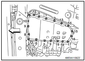
 : Front
- Tighten the oil pan bolts again clockwise from (1) shown to the specified torque.
Inspection
INSPECTION AFTER REMOVAL
Check oil pan for foreign material.
- If a large amount of worn material is found, clutch plate may be worn.
- If iron powder is found, bearings, gears, or clutch plates may be worn.
- If aluminum powder is found, bushing may be worn, or chips or burrs of aluminum casting parts may enter.
Check points where wear is found in all cases.
INSPECTION AFTER INSTALLATION
Check the CVT fluid level and leakage. Refer to TM-190, "Inspection".
 Air breather
Exploded View
Air breather
Air breather hose
Air breather tube
Transaxle assembly
: Vehicle front
Removal and Installation
REMOVAL
Remove air cleaner and air duct. Refer ...
 Input speed sensor
Exploded View
Input speed sensor
O-ring
Transaxle assembly
: Always replace after every
disassembly.
: N·m (kg-m, in-lb)
: Apply CVT fluid
Removal and Installation
REMOVAL
...
Other materials:
Terms
It is important to familiarize yourself with
the following terms before loading your
vehicle:
Curb Weight (actual weight of your
vehicle) - vehicle weight including:
standard and optional equipment, fluids,
emergency tools, and spare tire
assembly. This weight does not include
...
Heater and Air Conditioner (manual)
(if so equipped)
Heater and Air Conditioner
Fan speed control / system OFF dial / air
conditioning (A/C) button
Air flow control
buttons
Temperature control dial / MAX A/C button
Air recirculation button
Rear window and
outside mirror (if so
equipped) defroster but ...
Power supply and ground circuit
WITH INTELLIGENT KEY SYSTEM
WITH INTELLIGENT KEY SYSTEM : Diagnosis Procedure
Regarding Wiring Diagram information, refer to BCS-50, "Wiring Diagram".
1. CHECK FUSE
Check that the following fuse is not blown.
Terminal No.
Signal name
Fuse No.
161
BCM power sup ...
