
Nissan Rogue Service Manual: Primary speed sensor
Exploded View
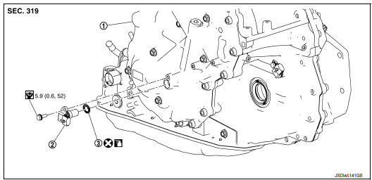
- Transaxle assembly
- O-ring
- Primary speed sensor
 : Always replace after every
disassembly.
 : N·m (kg-m, in-lb)
 : Apply CVT fluid
Removal and Installation
REMOVAL
- Remove the engine undercover. Refer to EXT-37, "ENGINE UNDER COVER : Removal and Installation".
- Disconnect the primary speed harness connector.
- Remove the primary speed sensor bolt and remove the primary speed sensor.
- Remove the O-ring from the primary speed sensor.
INSTALLATION
Installation is in the reverse order of removal.
CAUTION:
- Do not reuse O-ring.
- Apply CVT fluid to the O-ring.
Inspection and Adjustment
INSPECTION AFTER INSTALLATION
Check for CVT fluid leakage. Refer to TM-190, "Inspection".
ADJUSTMENT AFTER INSTALLATION
Adjust the CVT fluid level. Refer to TM-192, "Adjustment".
 Input speed sensor
Exploded View
Input speed sensor
O-ring
Transaxle assembly
: Always replace after every
disassembly.
: N·m (kg-m, in-lb)
: Apply CVT fluid
Removal and Installation
REMOVAL
...
 Output speed sensor
Exploded View
Transaxle assembly
Output speed sensor
O-ring
Always replace after every
disassembly.
: N·m (kg-m, in-lb)
: Apply CVT fluid
Removal and Installation
REMOVAL
...
Other materials:
Fuel level sensor unit, fuel filter
and fuel pump assembly
Exploded View
1. Lock ring
2. O-ring
3. Fuel filter and fuel pump assembly
4. Fuel level sensor and fuel tank temperature sensor
5. Lock ring
6. O-ring
7. Sub fuel level sensor assembly
8. Fuel tank
Fron
CAUTION:
Do not remove or disassemble parts unless instructed as shown.
R ...
CAN system (type 2)
MAIN LINE BETWEEN IPDM-E AND DLC CIRCUIT
Diagnosis Procedure
1.CHECK CONNECTOR
Turn the ignition switch OFF.
Disconnect the battery cable from the negative terminal.
Check the following terminals and connectors for damage, bend and
loose connection (connector side
an ...
Readiness for inspection/maintenance (I/M) test
WARNINGA vehicle equipped with All -Wheel Drive
(AWD) should never be tested using a two
wheel dynamometer (such as the dynamometers
used by some states for emissions
testing), or similar equipment. Make
sure you inform the test facility personnel
that your vehicle is equipp ...
