Nissan Rogue Service Manual: Power supply and ground circuit
Diagnosis Procedure
Regarding Wiring Diagram information, refer to PCS-24, "Wiring Diagram".
1. CHECK FUSE AND FUSIBLE LINKS
Check that the following IPDM E/R fuse or fusible links are not blown.
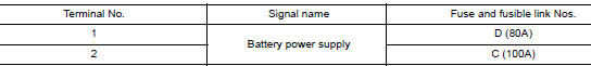
Is the fuse blown? YES >> Replace the blown fuse or fusible link after repairing the affected circuit.
NO >> GO TO 2.
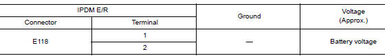
2. CHECK BATTERY POWER SUPPLY CIRCUIT
- Disconnect IPDM E/R connector E118.
- Check voltage between IPDM E/R connector E118 and ground.
Is the inspection result normal? YES >> GO TO 3.
NO >> Repair or replace harness or connectors.
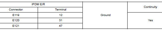
3. CHECK GROUND CIRCUIT
- Disconnect IPDM E/R connectors E119, E120 and E121.
- Check continuity between IPDM E/R connectors and ground.
Is the inspection result normal? YES >> Inspection End.
NO >> Repair or replace harness or connectors.
 U1000 CAN COMM CIRCUIT
Description
CAN communication allows a high rate of information transmission through the
two communication lines
(CAN-H line and CAN-L line) connecting various control units in the system. Each
...
 Parking brake switch
Component Function Check
1.CHECK PARKING BRAKE SWITCH OPERATION
Check that brake warning lamp in combination meter turns ON/OFF when parking
brake is operated.
Is the inspection result normal?
...
Other materials:
Using the system
Initialization
When the ignition switch is in the ON position,
NISSAN Voice Recognition is initialized, which
takes a few seconds. When completed, the system
is ready to accept voice commands. If
the button is pressed before the
initialization
completes, the system will announce: “Voice
...
Front wiper motor ground circuit
Diagnosis Procedure
Regarding Wiring Diagram information, refer to WW-22, "Wiring Diagram".
1. CHECK FRONT WIPER MOTOR GROUND CIRCUIT
Turn the ignition switch OFF.
Disconnect front wiper motor.
Check continuity between front wiper motor harness connector and
...
Coil spring
Exploded View
Upper seat
Coil spring
Lower seat
Rubber washer (LH/RH)
Rear suspension arm
Front
Removal and Installation - FWD
REMOVAL
Remove the rear wheel and tire using power tool.
Remove the bolt and separate the rear wheel sensor from the wheel h ...
