Nissan Rogue Service Manual: P0715 input speed sensor A
DTC Description
DTC DETECTION LOGIC
| DTC | CONSULT screen terms (Trouble diagnosis content) | DTC detection condition |
| P0715 | INPUT SPEED SENSOR A (Input/Turbine Speed Sensor A Circuit) | When 1 is satisfied and any of 2, 3 or 4 is satisfied:
|
POSSIBLE CAUSE
- Harness or connector (Primary speed sensor circuit is open or shorted)
- Primary speed sensor
FAIL-SAFE
- Start is slow
- Acceleration is slow
- Lock-up is not performed
DTC CONFIRMATION PROCEDURE
CAUTION: Be careful of the driving speed.
1.PREPARATION BEFORE WORK
If another "DTC CONFIRMATION PROCEDURE" occurs just before, turn ignition switch OFF and wait for at least 10 seconds, then perform the next test.
>> GO TO 2.
2.CHECK DTC DETECTION
- Start the engine.
- Drive the vehicle.
- Maintain the following conditions for 10 seconds or more.
Selector lever : “D” POSITION
Engine speed : 1,200 rpm or more
Vehicle speed : 40 km/h (25 MPH) or more
- Stop the vehicle.
- Check the first trip DTC.
Is “P0715” detected? YES >> Go to TM-126, "Diagnosis Procedure".
NO-1 >> To check malfunction symptom before repair: Refer to GI-41, "Intermittent Incident".
NO-2 >> Confirmation after repair: INSPECTION END
Diagnosis Procedure
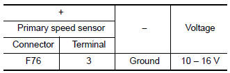
1.CHECK PRIMARY SPEED SENSOR POWER CIRCUIT
- Turn ignition switch OFF.
- Disconnect primary speed sensor connector.
- Turn ignition switch ON.
- Check voltage between primary speed sensor harness connector terminal and ground.
Is the inspection result normal? YES >> GO TO 2.
NO >> GO TO 6.
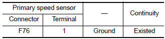
2.CHECK PRIMARY SPEED SENSOR GROUND CIRCUIT
Check continuity between primary speed sensor harness connector terminal and ground.
Is the inspection result normal? YES >> GO TO 3.
NO >> Repair or replace malfunctioning parts.
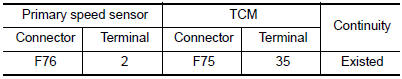
3.CHECK CIRCUIT BETWEEN PRIMARY SPEED SENSOR AND TCM (PART 1)
- Turn ignition switch OFF.
- Disconnect TCM connector.
- Check continuity between primary speed sensor harness connector terminal and TCM harness connector terminal.
Is the inspection result normal? YES >> GO TO 4.
NO >> Repair or replace malfunctioning parts.
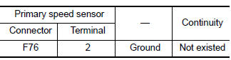
4.CHECK CIRCUIT BETWEEN PRIMARY SPEED SENSOR AND TCM (PART 2)
Check continuity between primary speed sensor harness connector terminal and ground.
Is the inspection result normal?
YES >> GO TO 5.
NO >> Repair or replace malfunctioning parts.
5.CHECK TCM INPUT SIGNALS
- Connect all of disconnected connectors.
- Lift the vehicle.
- Start the engine.
- Check frequency of primary speed sensor.
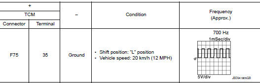
Is the inspection result normal? YES >> INSPECTION END
NO >> Replace primary speed sensor. Refer to TM-208, "Removal and Installation".
6.CHECK CIRCUIT BETWEEN IPDM E/R AND PRIMARY SPEED SENSOR
- Turn ignition switch OFF.
- Disconnect IPDM E/R connector.
- Check continuity between IPDM E/R harness connector terminal and primary speed sensor harness connector terminal.
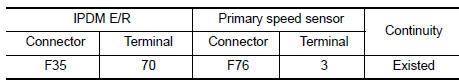
Is the check result normal? YES >> GO TO 7.
NO >> Repair or replace malfunctioning parts.
7.DETECT MALFUNCTIONING ITEMS
Check the following items:
- Open circuit or short circuit in harness between ignition switch and IPDM E/R. Refer to PG-15, "Wiring Diagram — Ignition Power Supply —".
- Short circuit in harness between IPDM E/R harness connector terminal 70 and primary speed sensor harness connector terminal 3.
- 10A fuse (No.46, located in the IPDM E/R). Refer to PG-68, "IPDM E/R Terminal Arrangement".
- IPDM E/R
Is the check result normal? YES >> INSPECTION END
NO >> Repair or replace malfunctioning parts.
 P0713 transmission fluid temperature sensor A
DTC Description
DTC DETECTION LOGIC
DTC
CONSULT screen terms
(Trouble diagnosis content)
DTC detection condition
P0713
FLUID TEMP SENSOR A
(Transmission Fluid Temperat ...
 P0717 input speed sensor A
DTC Description
DTC DETECTION LOGIC
DTC
CONSULT screen terms
(Trouble diagnosis content)
DTC detection condition
P0717
INPUT SPEED SENSOR A
(Input/Turbine Speed Sensor ...
Other materials:
P0181 FTT sensor
DTC Description
DTC DETECTION LOGIC
DTC No.
CONSULT screen terms
(Trouble diagnosis content)
DTC detecting condition
P0181
FTT SENSOR
(Fuel temperature sensor ″A″ circuit range/
performance)
A
Rationally incorrect voltage from the sensor is sent ...
Daytime running light system
The daytime running lights automatically illuminate
when the engine is started with the parking
brake released. The daytime running lights operate
with the headlight switch in the OFF position
or in the position. Turn the
headlight switch
to the position for full
illumination when
drivin ...
Liftgate
WARNING
Always be sure the liftgate has been
closed securely to prevent it from opening
while driving.
Do not drive with the liftgate open. This
could allow dangerous exhaust gases
to be drawn into the vehicle. Refer to
“Exhaust gas (carbon monoxide)â ...
