
Nissan Rogue Service Manual: P0451 EVAP control system pressure sensor
DTC Description
DTC DETECTION LOGIC
| DTC No. | CONSULT screen terms (Trouble diagnosis content) | DTC detecting condition |
| P0451 | EVAP SYS PRES SEN (Evaporative emission system pressure sensor/switch range/performance) | ECM detects a sloshing signal from the EVAP control system pressure sensor |
POSSIBLE CAUSE
- Harness or connectors (EVAP control system pressure sensor circuit is shorted.)
- EVAP control system pressure sensor
FAIL-SAFE
Not applicable
DTC CONFIRMATION PROCEDURE
NOTE: Never remove fuel filler cap during DTC confirmation procedure.
1.PRECONDITIONING
If DTC Confirmation Procedure has been previously conducted, always perform the following procedure before conducting the next test.
- Turn ignition switch OFF and wait at least 10 seconds.
- Turn ignition switch ON.
- Turn ignition switch OFF and wait at least 10 seconds.
 With CONSULT>>GO TO 2.
 Without CONSULT>>GO TO 5.
2.PERFORM DTC CONFIRMATION PROCEDURE-1
With CONSULT
- Start engine and let it idle for least 40 seconds.
NOTE: Do not depress accelerator pedal even slightly.
- Check 1st trip DTC.
Is 1st trip DTC detected? YES >> Proceed to EC-328, "Diagnosis Procedure".
NO >> GO TO 3.
3.PERFORM DTC CONFIRMATION PROCEDURE-2
With CONSULT
- Select “EVAP DIAG READY� in “DATA MONITOR� mode of “ENGINE�.
- Let it idle until “OFF� of “EVAP DIAG READY� changes to “ON�.
NOTE: It will take at most 2 hours until “OFF� of “EVAP DIAG READY� changes to “ON�.
- Turn ignition switch OFF and wait at least 90 minutes.
NOTE: Never turn ignition switch ON during 90 minutes.
- Turn ignition switch ON.
- Select “EVAP LEAK DIAG� in “DATA MONITOR� mode of “ENGINE�.
- Check that “EVAP LEAK DIAG� indication.
Which is displayed on CONSULT? CMPLT>> GO TO 4.
YET >> 1. Perform DTC CONFIRMATION PROCEDURE again.
2. GO TO 1.
4.PERFORM DTC CONFIRMATION PROCEDURE-3
 With CONSULT
Check 1st trip DTC.
Is 1st trip DTC detected? YES >> Proceed to EC-328, "Diagnosis Procedure".
NO >> INSPECTION END
5.PERFORM DTC CONFIRMATION PROCEDURE-4
 With GST
- Start engine and let it idle for least 40 seconds.
NOTE: Do not depress accelerator pedal even slightly.
- Check 1st trip DTC.
Is 1st trip DTC detected? YES >> Proceed to EC-328, "Diagnosis Procedure".
NO >> GO TO 6.
6.PERFORM DTC CONFIRMATION PROCEDURE-5
 With GST
- Let it idle for at least 2 hours.
- Turn ignition switch OFF and wait at least 90 minutes.
NOTE: Never turn ignition switch ON during 90 minutes.
- Turn ignition switch ON.
- Check 1st trip DTC.
Is 1st trip DTC detected? YES >> Proceed to EC-328, "Diagnosis Procedure".
NO >> INSPECTION END
Diagnosis Procedure
1.CHECK EVAP CONTROL SYSTEM PRESSURE SENSOR CONNECTOR FOR WATER
- Turn ignition switch OFF.
- Disconnect EVAP control system pressure sensor harness connector.
- Check sensor harness connector for water.
Water should not exist.
Is the inspection result normal? YES >> GO TO 2.
NO >> Repair or replace harness connector.
2.CHECK EVAP CONTROL SYSTEM PRESSURE SENSOR POWER SUPPLY
- Turn ignition switch ON.
- Check the voltage between EVAP control system pressure sensor harness connector and ground.
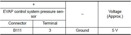
Is the inspection result normal? YES >> GO TO 4.
NO >> GO TO 3.
3.CHECK EVAP CONTROL SYSTEM PRESSURE SENSOR POWER SUPPLY CIRCUIT
- Turn ignition switch OFF.
- Disconnect ECM harness connector.
- Check the continuity between EVAP control system pressure sensor harness connector and ECM harness connector.
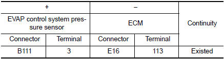
- Also check harness for short to ground and to power.
Is the inspection result normal? YES >> Perform the trouble diagnosis for power supply circuit.
NO >> Repair or replace error-detected parts
4.CHECK EVAP CONTROL SYSTEM PRESSURE SENSOR GROUND CIRCUIT
- Turn ignition switch OFF.
- Disconnect ECM harness connector.
- Check the continuity between EVAP control system pressure sensor harness connector and ECM harness connector.
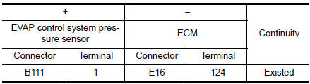
- Also check harness for short to power.
Is the inspection result normal? YES >> GO TO 5.
NO >> Repair or replace error-detected parts.
5.CHECK EVAP CONTROL SYSTEM PRESSURE SENSOR SIGNAL CIRCUIT
- Check the continuity between EVAP control system pressure sensor harness connector and ECM harness connector.
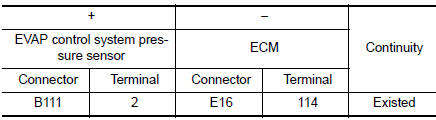
- Also check harness for short to ground and to power.
Is the inspection result normal? YES >> GO TO 6.
NO >> Repair or replace error-detected parts.
6.CHECK EVAP CONTROL SYSTEM PRESSURE SENSOR
Check the EVAP control system pressure sensor. Refer to EC-330, "Component Inspection".
Is the inspection result normal? YES >> GO TO 7.
NO >> Replace EVAP control system pressure sensor. Refer to FL-22, "Removal and Installation".
7.CHECK INTERMITTENT INCIDENT
Refer to GI-41, "Intermittent Incident".
>> INSPECTION END
Component Inspection
1.CHECK EVAP CONTROL SYSTEM PRESSURE SENSOR
- Turn ignition switch OFF.
- Remove EVAP control system pressure sensor with its harness
connector connected from EVAP canister.
Always replace O-ring with a new one.
- Install a vacuum pump to EVAP control system pressure sensor.
- Turn ignition switch ON and check output voltage between ECM harness connector and ground under the following conditions.

CAUTION:
- Always calibrate the vacuum pump gauge when using it.
- Do not apply below -93.3 kPa (-0.952 kg/cm2, -13.53 psi) or pressure over 101.3 kPa (1.033 kg/ cm2, 14.69 psi).
Is the inspection result normal?
YES >> INSPECTION END
NO >> Replace EVAP control system pressure sensor. Refer to FL-22, "Removal and Installation".
 P0448 EVAP canister vent control valve
DTC Description
DTC DETECTION LOGIC
DTC No.
CONSULT screen terms
(Trouble diagnosis content)
DTC detecting condition
P0448
VENT CONTROL VALVE
(Evaporative emission sys ...
 P0452 EVAP control system pressure sensor
DTC Description
DTC DETECTION LOGIC
DTC No.
CONSULT screen terms
(Trouble diagnosis content)
DTC detecting condition
P0452
EVAP SYS PRES SEN
(Evaporative emission syst ...
Other materials:
Air bags, seat belts and child restraints
Supplemental front-impact air bags
Occupant classification sensor (weight sensor)
Seat belts
Head restraints/headrests
Roof-mounted curtain side-impact and rollover supplemental air bag
2nd row center position top tether strap (located on ceiling) ...
Component parts
Component Parts Location
No.
Component
Function
1
Key switch
Transmits the key switch signal to the BCM.
Refer to SEC-115, "Component Parts Location" (without Intelligent Key
system) for detailed installation
location.
2
...
Wiring diagram
CHASSIS CONTROL
Wiring Diagram
...
