Nissan Rogue Service Manual: P014C, P014D, P015A, P015B, A/F sensor 1
DTC Description
DTC DETECTION LOGIC
To judge malfunctions, this diagnosis measures response time of the A/F signal computed by ECM from the A/ F sensor 1 signal. The time is compensated by engine operating (speed and load), fuel feedback control constant, and the A/F sensor 1 temperature index. Judgment is based on whether the compensated time (the A/F signal cycling time index) is inordinately long or not.
| DTC No. | CONSULT screen terms (Trouble diagnosis content) | DTC detecting condition |
| P014C | A/F SENSOR1 (B1) (O2 sensor slow response - rich to lean bank 1 sensor 1) |
|
| P014D | A/F SENSOR1 (B1) (O2 sensor slow response - lean to rich bank 1 sensor 1) | |
| P015A | A/F SENSOR1 (B1) (O2 sensor delayed response - rich to lean bank 1 sensor 1) | |
| P015B | A/F SENSOR1 (B1) (O2 sensor delayed response - lean to rich bank 1 sensor 1) |
POSSIBLE CAUSE
- Harness or connectors (The A/F sensor 1 circuit is open or shorted.)
- A/F sensor 1
FAIL-SAFE
Not applicable
DTC CONFIRMATION PROCEDURE
1.PRECONDITIONING
If DTC Confirmation Procedure has been previously conducted, always perform the following procedure before conducting the next test.
- Turn ignition switch OFF and wait at least 10 seconds.
- Turn ignition switch ON.
- Turn ignition switch OFF and wait at least 10 seconds.
TESTING CONDITION: Before performing the following procedure, confirm that battery voltage is more than 11 V at idle.
Do you have CONSULT? YES >> GO TO 2.
NO >> GO TO 6.
2.PERFORM DTC CONFIRMATION PROCEDURE-1
 With CONSULT
- Start engine and warm it up to normal operating temperature.
- Turn ignition switch OFF and wait at least 10 seconds.
- Turn ignition switch ON.
- Turn ignition switch OFF and wait at least 10 seconds.
- Start engine and keep the engine speed between 3,500 and 4,000 rpm for at least 1minute under no load.
- Let engine idle for 1 minute.
- Increase the engine speed up to about 3,600 rpm and keep it for 10 seconds.
- Fully release accelerator pedal and then let engine idle for about 1 minute.
- Check the items status of “DATA MONITOR” as follows.
NOTE: If “PRSNT” changed to “ABSNT”, refer to EC-157, "Component Function Check".
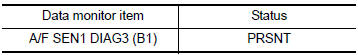
Is “PRSNT” displayed on CONSULT screen? YES >> GO TO 4.
NO >> GO TO 3.
3.PERFORM DTC CONFIRMATION PROCEDURE-2
 With CONSULT
Perform DTC confirmation procedure-1 again.
Is “PRSNT” displayed on CONSULT screen? YES >> GO TO 4.
NO >> Refer to EC-157, "Component Function Check".
4.PERFORM DTC CONFIRMATION PROCEDURE-2
 With CONSULT
- Wait for about 20 seconds at idle.
- Check the items status of “DATA MONITOR” as follows.
NOTE: If “CMPLT” changed to “INCMP”, refer to EC-157, "Component Function Check".
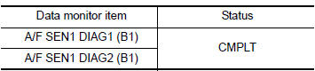
Is “CMPLT” displayed on CONSULT screen? YES >> GO TO 5.
NO >> Refer to EC-157, "Component Function Check".
5.PERFORM SELF-DIAGNOSIS
 With CONSULT
Check the “SELF-DIAG RESULT”.
Is any DTC detected? YES >> Proceed to EC-257, "Diagnosis Procedure".
NO >> INSPECTION END
6.CHECK AIR-FUEL RATIO SELF-LEARNING VALUE
 With GST
- Start engine and warm it up to normal operating temperature.
- Select Service $01 with GST.
- Calculate the total value of “Short term fuel trim” and “Long term fuel trim” indications.
Is the total percentage within ±15%? YES >> GO TO 8.
NO >> GO TO 7.
7.DETECT MALFUNCTIONING PART
Check the following.
- Intake air leaks
- Exhaust gas leaks
- Incorrect fuel pressure
- Lack of fuel
- Fuel injector
- Incorrect PCV hose connection
- PCV valve
- Mass air flow sensor
>> Repair or replace malfunctioning part.
8.PERFORM DTC CONFIRMATION PROCEDURE
- Turn ignition switch OFF and wait at least 10 seconds.
- Turn ignition switch ON.
- Turn ignition switch OFF and wait at least 10 seconds.
- Start engine and keep the engine speed between 3,500 and 4,000 rpm for at least 1 minute under no load.
- Let engine idle for 1 minute.
- Increase the engine speed up to about 3,600 rpm and keep it for 10 seconds.
- Fully release accelerator pedal and then let engine idle for about 1 minute.
- Check 1st trip DTC.
Is 1st trip DTC detected? YES >> Proceed to EC-257, "Diagnosis Procedure".
NO >> INSPECTION END
Diagnosis Procedure
1.RETIGHTEN A/F SENSOR 1
Loosen and retighten the A/F sensor 1. Refer to EM-29, "Exploded View".
>> GO TO 2.
2.CHECK EXHAUST GAS LEAK
- Start engine and run it at idle.
- Listen for an exhaust gas leak before three way catalyst (manifold).
Is exhaust gas leak detected? YES >> Repair or replace.
NO >> GO TO 3.
3.CHECK FOR INTAKE AIR LEAK
Listen for an intake air leak after the mass air flow sensor.
Is intake air leak detected? YES >> Repair or replace.
NO >> GO TO 4.
4.CLEAR THE MIXTURE RATIO SELF-LEARNING VALUE
- Clear the mixture ratio self-learning value. Refer to EC-143, "Work Procedure".
- Run engine for at least 10 minutes at idle speed.
Is the 1st trip DTC P0171 or P172 detected? Is it difficult to start engine? YES >> Perform trouble diagnosis for DTC P0171 or P0172. Refer to EC-260, "DTC Description" or EC- 265, "DTC Description".
NO >> GO TO 5.
5.CHECK AIR FUEL RATIO (A/F) SENSOR 1 POWER SUPPLY CIRCUIT
- Disconnect A/F sensor 1 harness connector.
- Turn ignition switch ON.
- Check the voltage between A/F sensor 1 harness connector and ground.
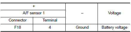
Is the inspection result normal? YES >> GO TO 6.
NO >> Repair or replace error-detected parts.
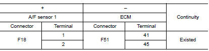
6.CHECK A/F SENSOR 1 INPUT SIGNAL CIRCUIT
- Turn ignition switch OFF.
- Disconnect ECM harness connector.
- Check the continuity between A/F sensor 1 harness connector and ECM harness connector.
- Check the continuity between A/F sensor 1 harness connector and ground, or ECM harness connector and ground.
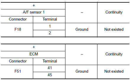
- Also check harness for short to power.
Is the inspection result normal? YES >> GO TO 7.
NO >> Repair or replace error-detected parts.
7.CHECK AIR FUEL RATIO (A/F) SENSOR 1 HEATER
Refer to EC-186, "Component Inspection".
Is the inspection result normal? YES >> GO TO 8.
NO >> GO TO 11.
8.CHECK MASS AIR FLOW SENSOR
Refer to EC-200, "Component Inspection".
Is the inspection result normal? YES >> GO TO 9.
NO >> Replace mass air flow sensor. Refer to EM-24, "Exploded View".
9.CHECK PCV VALVE
Refer to EC-498, "Inspection".
Is the inspection result normal? YES >> GO TO 10.
NO >> Repair or replace PCV valve. Refer to EC-14, "Component Parts Location".
10.CHECK INTERMITTENT INCIDENT
Perform GI-41, "Intermittent Incident".
Is the inspection result normal? YES >> GO TO 11.
NO >> Repair or replace.
11.REPLACE AIR FUEL RATIO (A/F) SENSOR 1
Replace air fuel ratio (A/F) sensor 1. Refer to EM-29, "Exploded View".
CAUTION:
- Discard any sensor which has been dropped from a height of more than 0.5 m (19.7 in) onto a hard surface such as a concrete floor; use a new one.
- Before installing new sensor, clean exhaust system threads using Oxygen Sensor Thread Cleaner [commercial service tool (J-43897-18 or J43897-12)] and approved Anti-seize Lubricant (commercial service tool).
>> INSPECTION END
 P0139 HO2S2
DTC Description
DTC DETECTION LOGIC
The heated oxygen sensor 2 has a much longer switching time
between rich and lean than the air fuel ratio (A/F) sensor 1. The oxygen
storage capacity of the thr ...
 P0171 fuel injection system function
DTC Description
DTC DETECTION LOGIC
With the Air/Fuel Mixture Ratio Self-Learning Control, the actual mixture
ratio can be brought closely to the
theoretical mixture ratio based on the mixture ra ...
Other materials:
Squeak and rattle trouble diagnoses
Work Flow
CUSTOMER INTERVIEW
Interview the customer if possible, to determine the conditions that exist
when the noise occurs. Use the Diagnostic
Worksheet during the interview to document the facts and conditions when the
noise occurs and any
customer's comments; refer to RF-47, &qu ...
Preparation
Special Service Tool
The actual shape of the tools may differ from those illustrated here.
Tool number
(TechMate No.)
Tool name
Description
—
(165-GR8-1200KIT-NI)
Multitasking battery and electrical diagnostic
station
Testing batteries, starti ...
Basic inspection
DIAGNOSIS AND REPAIR WORKFLOW
Work Flow (With GR8-1200 NI)
STARTING SYSTEM DIAGNOSIS WITH GR8-1200 NI
To test the starting system, use the following special service tool:
GR8-1200 NI Multitasking battery and electrical diagnostic station
NOTE:
Refer to the diagnostic station Instruc ...
