Nissan Rogue Service Manual: P0706 transmission range sensor A
DTC Description
DTC DETECTION LOGIC
| DTC | CONSULT screen terms (Trouble diagnosis content) | DTC detection condition |
| P0706 | T/M RANGE SENSOR A (Transmission Range Sensor A Circuit Range/ Performance) | When all of the following conditions are satisfied and this state is
maintained
for 30 seconds:
|
POSSIBLE CAUSE
- Harness or connector (Open circuit between ignition switch and transmission range switch/open circuit between transmission range switch and TCM)
- Transmission range switch
- Control cable
Harness or connector (CAN communication line is error)
FAIL-SAFE
- Shift position indicator on combination meter is not displayed
- Selector shock is large
- Start is slow
- Acceleration is slow
- Lock-up is not performed
DTC CONFIRMATION PROCEDURE
1.PREPARATION BEFORE WORK
If another "DTC CONFIRMATION PROCEDURE" occurs just before, turn ignition switch OFF and wait for at least 10 seconds, then perform the next test.
>> GO TO 2.
2.PERFORM DTC CONFIRMATION PROCEDURE
- Turn ignition switch ON.
- Shift the selector lever through entire positions from “P” to “L”. (Hold the selector lever at each position for 40 seconds or more.)
- Check the first trip DTC.
Is “P0706” detected? YES >> Go to TM-113, "Diagnosis Procedure".
NO-1 >> To check malfunction symptom before repair: Refer to GI-41, "Intermittent Incident".
NO-2 >> Confirmation after repair: INSPECTION END
Diagnosis Procedure
1.ADJUSTMENT OF CONTROL CABLE
Adjust control cable. Refer to TM-196, "Inspection".
>> GO TO 2.
2.PERFORM DTC CONFIRMATION PROCEDURE
 With CONSULT
- Turn ignition switch ON.
- Select “Self Diagnostic Results” in “TRANSMISSION”.
- Touch “Erase”.
- Perform “DTC CONFIRMATION PROCEDURE". Refer to TM-113, "DTC Description".
Is “P0706” detected?
YES >> GO TO 3.
NO >> INSPECTION END
3.CHECK POWER CIRCUIT
- Turn ignition switch OFF.
- Disconnect transmission range switch connector.
- Turn ignition switch ON.
- Check voltage between transmission range switch harness connector terminal and ground.
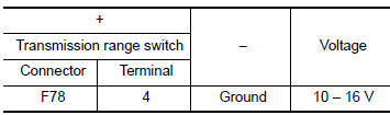
Is the inspection result normal? YES >> GO TO 4.
NO >> GO TO 7.
4.CHECK CIRCUIT BETWEEN TRANSMISSION RANGE SWITCH AND TCM (PART 1)
- Turn ignition switch OFF.
- Disconnect TCM connector.
- Check continuity between transmission range switch harness connector terminals and TCM harness connector terminals.
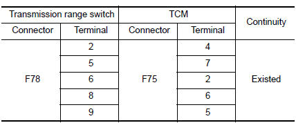
Is the inspection result normal? YES >> GO TO 5.
NO >> Repair or replace malfunctioning parts.
5.CHECK CIRCUIT BETWEEN TRANSMISSION RANGE SWITCH AND TCM (PART 2)
Check continuity between transmission range switch harness connector terminals and ground.
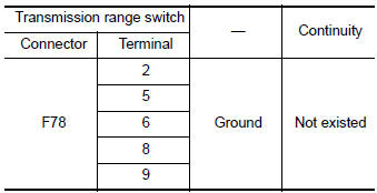
Is the inspection result normal? YES >> GO TO 6.
NO >> Repair or replace malfunctioning parts.
6.CHECK TRANSMISSION RANGE SWITCH
Check transmission range switch. Refer to TM-115, "Component Inspection".
Is the inspection result normal? YES >> INSPECTION END
NO >> Repair or replace malfunctioning parts.
7.CHECK CIRCUIT BETWEEN IPDM E/R AND TRANSMISSION RANGE SWITCH
- Turn ignition switch OFF.
- Disconnect IPDM E/R connector.
- Check continuity between IPDM E/R harness connector terminal and transmission range switch harness connector terminal.
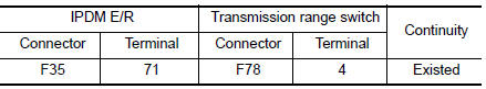
Is the check result normal? YES >> GO TO 8.
NO >> Repair or replace malfunctioning parts.
8.DETECT MALFUNCTIONING ITEMS
Check the following items:
- Open circuit or short circuit in harness between ignition switch and IPDM E/R. Refer to PG-15, "Wiring Diagram — Ignition Power Supply —".
- Short circuit in harness between IPDM E/R harness connector terminal 71 and transmission range switch harness connector terminal 4.
- 10A fuse (No. 50, located in the IPDM E/R). Refer to PG-68, "IPDM E/R Terminal Arrangement".
- IPDM E/R
Is the check result normal? YES >> INSPECTION END
NO >> Repair or replace malfunctioning parts.
Component Inspection
1.CHECK TRANSMISSION RANGE SWITCH
Check continuity between transmission range switch connector terminals.
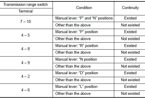
Is the inspection result normal? YES >> INSPECTION END
NO >> There is a malfunction of transmission range switch. Replace transaxle assembly. Refer to TM- 220, "Removal and Installation".
 P0705 transmission range sensor A
DTC Description
DTC DETECTION LOGIC
DTC
CONSULT screen terms
(Trouble diagnosis content)
DTC detection condition
P0705
T/M RANGE SENSOR A
[Transmission Range Sensor A ...
 P0711 transmission fluid temperature sensor A
DTC Description
DTC DETECTION LOGIC
DTC
CONSULT screen terms
(Trouble diagnosis content)
DTC detection condition
P0711
FLUID TEMP SENSOR A
(Transmission Fluid Temperat ...
Other materials:
Maintenance precautions
When performing any inspection or maintenance
work on your vehicle, always take care to prevent
serious accidental injury to yourself or damage to
the vehicle. The following are general precautions
which should be closely observed.
WARNING
Park the vehicle on a level surface, a ...
Steering column
Exploded View
Steering column
Floor cover
Floor seal
Removal and Installation
CAUTION:
Any time the ignition switch has been disconnected, removed or
installed, the keys must be re-registered
in the BCM. Refer to CONSULT operations manual.
Do not ...
Door switch
WITH INTELLIGENT KEY
WITH INTELLIGENT KEY : Component Function Check
1.CHECK FUNCTION
Select "DOOR LOCK" of "BCM" using CONSULT.
Select "DOOR SW-DR", "DOOR SW-AS", "DOOR SW-RL", "DOOR SW-RR", in "Data
Monitor&quo ...
