Nissan Rogue Service Manual: P0101 MAF sensor
DTC Description
DTC DETECTION LOGIC
| DTC No. | CONSULT screen terms (Trouble diagnosis content) | DTC detecting condition |
| P0101 | MAF SEN/CIRCUIT-B1 (Mass or volume air Flow ″A″ circuit range/ performance) |
|
POSSIBLE CAUSE
- Harness or connectors (MAF sensor circuit is open or shorted.)
- Intake air leaks
- MAF sensor
- EVAP control system pressure sensor
- Intake air temperature sensor
- Sensor power supply 2 circuit
FAIL-SAFE
- Traveling control mode (Accelerator angle variation control)
- Traveling control mode (Engine output control)
- Device fix mode
DTC CONFIRMATION PROCEDURE
1.CHECK DTC PRIORITY
If DTC P0101 is displayed with other DTC, first perform the trouble diagnosis for other DTC.
Is applicable DTC detected? YES >> Perform diagnosis of applicable. Refer to EC-93, "DTC Index".
NO >> GO TO 2.
2.PRECONDITIONING
If DTC CONFIRMATION PROCEDURE has been previously conducted, always perform the following procedure before conducting the next test.
- Turn ignition switch OFF and wait at least 10 seconds.
- Turn ignition switch ON.
- Turn ignition switch OFF and wait at least 10 seconds.
>> GO TO 3.
3.PERFORM DTC CONFIRMATION PROCEDURE
- Start engine and warm it up to normal operating temperature.
- Drive the vehicle for at least 5 seconds under the following conditions:
CAUTION: Always drive vehicle at safe speed.

NOTE:
- The gear must be fixed while driving the vehicle.
- Keep the accelerator pedal as steady as possible during cruising.
- Check 1st trip DTC.
Is 1st trip DTC detected? YES >> Proceed to EC-199, "Diagnosis Procedure".
NO >> INSPECTION END
Diagnosis Procedure
1.CHECK DTC PRIORITY
If DTC P0101 is displayed with other DTC, first perform the trouble diagnosis for other DTC.
Is applicable DTC detected? YES >> Perform diagnosis of applicable. Refer to EC-93, "DTC Index".
NO >> GO TO 2.
2.CHECK INTAKE SYSTEM
Check the following for connection.
- Air duct
- Vacuum hoses
- Intake air passage between air duct and intake manifold
Is the inspection result normal? YES >> GO TO 3.
NO >> Reconnect the parts.
3.CHECK MASS AIR FLOW (MAF) SENSOR POWER SUPPLY
- Turn ignition switch OFF.
- Disconnect MAF sensor harness connector.
- Turn ignition switch ON.
- Check the voltage between MAF sensor harness connector and ground.

Is the inspection result normal? YES >> GO TO 5.
NO >> GO TO 4.
4.CHECK SENSOR POWER SUPPLY 2 CIRCUIT
Perform EC-484, "Diagnosis Procedure".
Is the inspection result normal? YES >> Perform the trouble diagnosis for power supply circuit.
NO >> Repair or replace error-detected parts.
5.CHECK MAF SENSOR GROUND CIRCUIT
- Turn ignition switch OFF.
- Disconnect ECM harness connector.
- Check the continuity between MAF sensor harness connector and ECM harness connector.
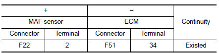
- Also check harness for short to power.
Is the inspection result normal? YES >> GO TO 6.
NO >> Repair or replace error-detected parts.
6.CHECK MAF SENSOR INPUT SIGNAL CIRCUIT
- Check the continuity between MAF sensor harness connector and ECM harness connector.
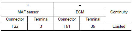
- Also check harness for short to ground and to power.
Is the inspection result normal? YES >> GO TO 7.
NO >> Repair or replace error-detected parts
7.CHECK INTAKE AIR TEMPERATURE SENSOR
Check the intake air temperature sensor. Refer to EC-207, "Component Inspection".
Is the inspection result normal? YES >> GO TO 8.
NO >> Replace MAF sensor (with intake air temperature sensor). Refer to EM-24, "Exploded View".
8.CHECK EVAP CONTROL SYSTEM PRESSURE SENSOR
Check the EVAP control system pressure sensor. Refer to EC-330, "Component Inspection".
Is the inspection result normal? YES >> GO TO 9.
NO >> Replace EVAP control system pressure sensor. Refer to FL-22, "Removal and Installation".
9.CHECK MAF SENSOR
Check the MAF sensor. Refer to EC-200, "Component Inspection".
Is the inspection result normal? YES >> GO TO 10.
NO >> Replace MAF sensor. Refer to EM-24, "Exploded View".
10.CHECK INTERMITTENT INCIDENT
Refer to GI-41, "Intermittent Incident".
>> INSPECTION END
Component Inspection
1.CHECK MASS AIR FLOW SENSOR-1
 With CONSULT
- Turn ignition switch OFF.
- Reconnect all harness connectors disconnected.
- Start engine and warm it up to normal operating temperature.
- Connect CONSULT and select “DATA MONITOR” mode of “ENGINE”.
- Select “MASS AIR FLOW SENSOR (Hz)” and check indication.

*: Check for linear frequency rise in response to engine being increased to about 4,000 rpm.
Is the inspection result normal? YES >> INSPECTION END
NO >> GO TO 2.
2.CHECK FOR THE CAUSE OF UNEVEN AIR FLOW THROUGH MASS AIR FLOW SENSOR
- Turn ignition switch OFF.
- Check for the cause of uneven air flow through mass air flow sensor. Refer to the following.
- Crushed air ducts
- Malfunctioning seal of air cleaner element
- Uneven dirt of air cleaner element
- Intake valve deposits
- Improper specification of intake air system parts
Is the inspection result normal? YES >> GO TO 4.
NO >> GO TO 3.
3.CHECK MASS AIR FLOW SENSOR-2
 With CONSULT
- Repair or replace malfunctioning part.
- Start engine and warm it up to normal operating temperature.
- Connect CONSULT and select “DATA MONITOR” mode of “ENGINE”.
- Select “MASS AIR FLOW SENSOR (Hz)” and check indication.
| Monitor item | Condition | Value |
| MASS AIR FLOW SENSOR (Hz) | Ignition switch ON (Engine stopped.) | Approx. 3500 Hz |
| Idle (Engine is warmed-up to normal operating temperature.) | 3500- 4100 Hz | |
| 2,500 rpm (Engine is warmed-up to normal operating temperature.) | 5000 - 5600 Hz | |
| Idle to about 4,000 rpm | 3500 - 4100 Hz to Approx. 6300 Hz* |
*: Check for linear frequency rise in response to engine being increased to about 4,000 rpm.
Is the inspection result normal? YES >> INSPECTION END
NO >> GO TO 4.
4.CHECK MASS AIR FLOW SENSOR-3
With CONSULT
- Turn ignition switch OFF.
- Disconnect mass air flow sensor harness connector and reconnect it again.
- Start engine and warm it up to normal operating temperature.
- Connect CONSULT and select “DATA MONITOR” mode of “ENGINE”.
- Select “MASS AIR FLOW SENSOR (Hz)” and check indication.
| Monitor item | Condition | Value |
| MASS AIR FLOW SENSOR (Hz) | Ignition switch ON (Engine stopped.) | Approx. 3500 Hz |
| Idle (Engine is warmed-up to normal operating temperature.) | 3500- 4100 Hz | |
| 2,500 rpm (Engine is warmed-up to normal operating temperature.) | 5000 - 5600 Hz | |
| Idle to about 4,000 rpm | 3500 - 4100 Hz to Approx. 6300 Hz* |
*: Check for linear frequency rise in response to engine being increased to about 4,000 rpm.
Is the inspection result normal? YES >> INSPECTION END
NO >> Clean or replace mass air flow sensor. Refer to EM-24, "Exploded View".
 P0078 EVT control solenoid valve
DTC Description
DTC DETECTION LOGIC
DTC No.
CONSULT screen terms
(Trouble diagnosis content)
DTC detecting condit
P0078
EX V/T ACT/CIRC-B1
(Exhaust valve control solen ...
 P0102, P0103 MAF sensor
DTC Description
DTC DETECTION LOGIC
DTC No.
CONSULT screen terms
(Trouble diagnosis content)
DTC detecting condition
P0102
MAF SEN/CIRCUIT-B1
(Mass or volume air flow ...
Other materials:
Steering column covers
Removal and Installation
REMOVAL
Release gap hider (1) pawls from the steering column upper
cover (2).
: Pawl
Remove steering column cover screws (A)
NOTE:
Rotate steering wheel to access steering column cover screws.
Release steering column upper cover (1) pawls u ...
Component parts
Component Parts Location
No.
Component
Function
1
Key switch
Transmits the key switch signal to the BCM.
Refer to SEC-115, "Component Parts Location" (without Intelligent Key
system) for detailed installation
location.
2
...
Push-Button Ignition Switch (if so equipped)
WARNINGDo not operate the push-button ignition
switch while driving the vehicle except in
an emergency. (The engine will stop when
the ignition switch is pushed 3 consecutive
times in quick succession or the ignition
switch is pushed and held for more
than 2 seconds.) If the ...
