Nissan Rogue Service Manual: Key switch signal circuit (without intelligent key)
Description
Transmits a key switch signal to the BCM.
Component Function Check
1. CHECK BCM INPUT SIGNAL
Select "Data Monitor" for "BCM" and check the "KEY ON SW" monitor value.

Is the inspection result normal? YES >> Inspection End.
NO >> Refer to WCS-47, "Diagnosis Procedure".
Diagnosis Procedure
Regarding Wiring Diagram information, refer to WCS-29, "Wiring Diagram".
1. CHECK BCM INPUT SIGNAL
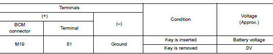
Check voltage between BCM harness connector M19 terminal 81 and ground.
Is the inspection result normal? YES >> Inspection End.
NO >> GO TO 2.
2. CHECK KEY SWITCH CIRCUIT
- Disconnect BCM connector M19 and key switch.
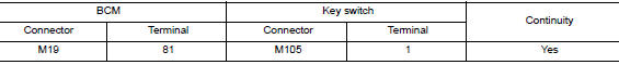
- Check continuity between BCM harness connector M19 terminal 81 and key switch harness connector M105 terminal 1.
- Check continuity between BCM harness connector M19 terminal 81 and ground.

Is the inspection result normal? YES >> GO TO 3.
NO >> Repair or replace harness or connector.
3. CHECK KEY SWITCH POWER SUPPLY CIRCUIT
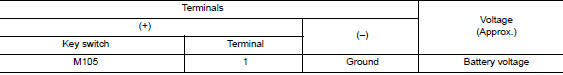
Check voltage between key switch harness connector M105 terminal 1 and ground.
Is the inspection result normal? YES >> GO TO 4.
NO >> Repair or replace harness or connector.
4. CHECK KEY SWITCH GROUND CIRCUIT
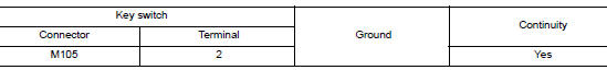
Check continuity between key switch harness connector M105 terminal 2 and ground.
Is the inspection result normal? YES >> Replace key switch.
NO >> Repair or replace harness or connector.
Component Inspection
1. CHECK KEY SWITCH
- Turn ignition switch OFF.
- Disconnect key switch.
- Check continuity between key switch terminals 1 and 2.

Is the inspection result normal? YES >> Inspection End.
NO >> Replace key switch.
 Parking brake switch signal circuit
Component Function Check
1.CHECK PARKING BRAKE SWITCH OPERATION
Check that brake warning lamp in combination meter turns ON/OFF when parking
brake is actuated.
Is the inspection result normal?
...

Other materials:
How to use this manual
How to use this manual
Description
This volume explains ŌĆ£Removal, Disassembly, Installation, Inspection and
AdjustmentŌĆØ and ŌĆ£Trouble DiagnosesŌĆØ.
Terms
The captions WARNING and CAUTION warn you of steps that must be followed
to prevent personal injury
and/or damage to some par ...
Vehicle Dynamic Control (VDC) system
The Vehicle Dynamic Control (VDC) system uses
various sensors to monitor driver inputs and vehicle
motion. Under certain driving conditions,
the VDC System helps to perform the following
functions:
Controls brake pressure to reduce wheel
slip on 1 slipping drive wheel so power is
t ...
Precaution
Precaution for Supplemental Restraint System (SRS) "AIR BAG" and "SEAT
BELT
PRE-TENSIONER"
The Supplemental Restraint System such as ŌĆ£AIR BAGŌĆØ and ŌĆ£SEAT BELT PRE-TENSIONERŌĆØ,
used along
with a front seat belt, helps to reduce the risk or severity of injury to the
...
