
Nissan Rogue Service Manual: CVT shift selector
Exploded View
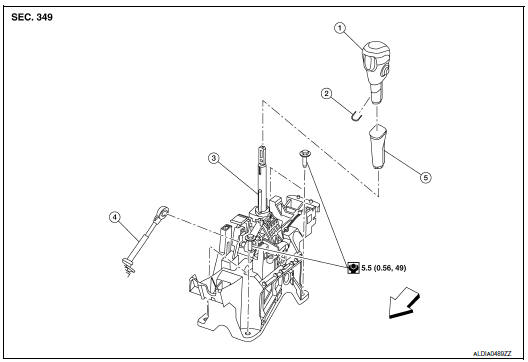
- Shift selector knob
- Lock pin
- Shift selector assembly
- Control cable
- Shift selector knob cover
 Front
Front
Removal and installation
REMOVAL
- Apply the parking brake.
CAUTION: Make sure the vehicle cannot move with the parking brake applied.
- Move the shift selector with the following procedure.
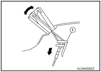
- Remove shift lock override button cover (1) using suitable tool.

: Front
- Insert suitable tool into opening to depress the shift lock override
button (1) in the direction (
 ) shown. Move shift selector
to “n� position while depressing shift lock override button.
) shown. Move shift selector
to “n� position while depressing shift lock override button.
Front
- Remove the shift selector knob with the following procedure.
- Slide the selector lever knob cover (1) down.
CAUTION: Do not damage the knob cover.
- Pull out the lock pin (2) from the selector lever knob (3).
- Pull the selector lever knob and the selector lever knob cover upwards to remove them.
- Remove the center console assembly. Refer to IP-18, "Removal and Installation".
- Shift the selector lever to “P� position.

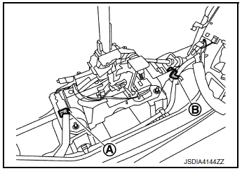
- Disconnect the shift selector connector (A) and remove harness clip (B).
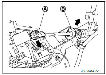
- Disconnect the tip (A) of control cable and remove socket (B) from the shift selector assembly.
- Remove the shift selector assembly nuts (
) and remove the
shift selector assembly from the vehicle.

INSTALLATION
Installation is in the reverse order of removal.
- Pay attention to the following when connecting the control cable to the shift selector assembly.
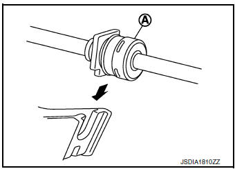
- When connecting the control cable (1) to the shift selector assembly (2), face the grooved surface of the rib (A) up and insert the control cable until it stops.
NOTE: Apply multi-purpose grease to control cable eye before installation.

- Install the socket (A) onto the shift selector assembly.
CAUTION:
- Place the socket onto the shift selector assembly, then fasten it in place from above.
- Check that the pulling on the socket does not disconnect it.
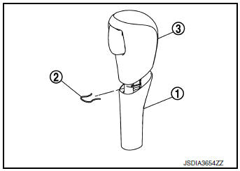
- Follow the procedure below and place the selector lever knob onto the shift selector.
- Install the lock pin (2) onto the selector lever knob (3).
- Install the knob cover (1) onto the selector lever knob.
- Shift the selector lever to “N� position.
- Insert the selector lever knob into the selector lever until a slight touch is felt.
- Press and hold the selector lever knob button and insert selector
lever knob into selector lever until it clanks.
CAUTION: Do not strike the selector lever knob to press it into place.
- After installing selector lever knob, pull the knob to check that it does not become disconnected
Inspection
INSPECTION AFTER INSTALLATION
- Check the shift selector position. Refer to TM-92, "Inspection".
- Check that shift lock can be forcible release. Refer to TM-29, "SHIFT LOCK SYSTEM : System Description".

 Control cable
Exploded View
Shift selector
Control cable
Retainer grommet
Lock plate
Bracket
Manual lever
Transaxle assembly
Front
Removal and Installation
CAUTION:
Always apply ...
Other materials:
Periodic maintenance
FRONT WHEEL HUB AND KNUCKLE
Inspection
Move the wheel hub and bearing in an axial direction by hand to verify
that looseness of wheel hub and
bearing exists. If any looseness exists, replace the wheel hub and bearing.
Axial end play : Refer to FAX-32, "Wheel Bearing".
Rota ...
Ignition signal
Component Function Check
1.INSPECTION START
Turn ignition switch OFF, and restart engine.
Does the engine start?
YES-1 >> With CONSULT: GO TO 2.
YES-2 >> Without CONSULT: GO TO 3.
NO >> Proceed to EC-470, "Diagnosis Procedure".
2.CHECK IGNITION SIGNAL FUNCTIO ...
U0101 CAN comm circuit
Description
CAN (Controller Area Network) is a serial communication line for real time
application. It is an on-vehicle multiplex
communication line with high data communication speed and excellent error
detection ability. Many electronic
control units are equipped onto a vehicle, and each co ...
