Nissan Rogue Service Manual: Instrument panel assembly
Exploded View
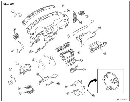
- Defroster grille
- Center speaker grille (if equipped)
- Side ventilator grille (LH)
- Instrument side finisher (LH)
- Knee protector
- Instrument finisher A
- Cluster lid A
- Instrument finisher B (without pushbutton ignition)
- Instrument finisher B (with pushbutton ignition)
- Upper switch carrier
- Lower switch carrier
- Instrument lower panel LH
- Data link cover
- Steering column upper cover
- Steering column lower cover
- Steering lock escutcheon
- Center ventilator grille
- Audio unit (DISPLAY AUDIO) / AV control unit (NAVIGATION WITHOUT BOSE) (NAVIGATION WITH BOSE)
- A/C switch assembly (AUTOMATIC AIR CONDITONING) / front air control (MANUAL AIR CONDITIONING)
- Cluster lid C
- Glove box assembly
- Glove box housing
- Instrument finisher E
- Instrument side finisher (RH)
- Side ventilator grille (RH)
- Instrument panel
INSTRUMENT PANEL ASSEMBLY
INSTRUMENT PANEL ASSEMBLY : Removal and Installation
CAUTION:
- Be careful not to scratch instrument panel pad and other parts.
- Whenever a suitable tool is used, always wrap a cloth around the end of the tool to protect components from damage.
- Before servicing, turn ignition switch OFF, disconnect both battery terminals then wait at least three minutes.
REMOVAL
- Disconnect the negative and positive battery terminals, then wait at least three minutes. Refer to PG-75, "Removal and Installation (Battery)".
- Remove dash side finishers (LH/RH). Refer to INT-24, "DASH SIDE FINISHER : Removal and Installation".
- Remove front pillar finishers (LH/RH). Refer to INT-20, "FRONT PILLAR FINISHER : Removal and Installation".
- Remove combination switch. Refer to EXL-124, "Removal and Installation".
- Remove center console assembly. Refer to IP-18, "Removal and Installation".
- Remove combination meter. Refer to MWI-82, "Removal and Installation".
- Remove audio unit (DISPLAY AUDIO). Refer to AV-64, "Removal and Installation".
- Remove AV control unit. Refer to AV-209, "Removal and Installation" (NAVIGATION WITHOUT BOSE) or AV-376, "Removal and Installation" (NAVIGATION WITH BOSE).
- Remove instrument finisher A. Refer to IP-15, "INSTRUMENT FINISHER A : Removal and Installation".
- Remove instrument finisher B. Refer to IP-16, "INSTRUMENT FINISHER B : Removal and Installation".
- Remove instrument finisher E. Refer to IP-16, "INSTRUMENT FINISHER E : Removal and Installation".
- Remove glove box assembly and housing. Refer to IP-23, "Removal and Installation".
- Remove instrument panel assembly screws.
- Disconnect the harness connectors from the instrument panel assembly and remove.
INSTALLATION
Installation is in the reverse order of removal.
- If replacing the instrument panel, transfer all the necessary parts to the new instrument panel.
INSTRUMENT FINISHER A
INSTRUMENT FINISHER A : Removal and Installation
REMOVAL
- Remove side ventilator grille (LH). Refer to VTL-13, "SIDE VENTILATOR GRILLE : Removal and Installation".
- Remove instrument lower panel LH. Refer to IP-22, "Removal and Installation".
- Release the instrument finisher A clips and pawls using a suitable tool.
 : Pawl
 : Metal clip
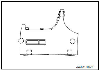
- Disconnect the harness connector from instrument finisher A and remove.
INSTALLATION
Installation is in the reverse order of removal.
INSTRUMENT FINISHER B
INSTRUMENT FINISHER B : Removal and Installation
REMOVAL
- Remove front air control or A/C switch assembly. Refer to HAC-181, "Removal and Installation" (MANUAL AIR CONDITIONING) or HAC-102, "Removal and Installation" (AUTOMATIC AIR CONDITIONING).
- Release the instrument finisher B clips and pawls using a suitable tool.
 : Pawl
 : Metal clip
- Disconnect the harness connector (if equipped) and remove instrument finisher B.
INSTALLATION
Installation is in the reverse order of removal.
INSTRUMENT FINISHER E
INSTRUMENT FINISHER E : Removal and Installation
REMOVAL
- Remove side ventilator grille (RH). Refer to VTL-13, "SIDE VENTILATOR GRILLE : Removal and Installation".
- Release the clips and pawls using a suitable tool and remove instrument finisher E.
Pawl
: Metal clip
INSTALLATION
Installation is in the reverse order of removal

 Steering column covers
Removal and Installation
REMOVAL
Release gap hider (1) pawls from the steering column upper
cover (2).
: Pawl
Remove steering column cover screws (A)
NOTE:
Rotate steering w ...
Other materials:
ECU diagnosis information
BCM
Reference Value
NOTE:
The Signal Tech II Tool (J-50190) can be used to perform the following
functions. Refer to the Signal Tech II
User Guide for additional information.
Activate and display TPMS sensor IDs
Display tire pressure reported by the TPMS sensor
Read T ...
Adjusting the screen
The procedure for adjusting the quality of the
screen differs depending on the type of screen
present on the vehicle.
For vehicles without Navigation System:
Press the ENTER/SETTING or
ENTER/AUDIO button.
Turn the TUNE/SCROLL or TUNE/FOLDER
knob to highlight the тАЬBri ...
Symptom diagnosis
PUSH-BUTTON IGNITION SWITCH DOES NOT OPERATE
Description
Check that vehicle Operating Conditions are as listed in тАЬConditions of
VehicleтАЭ below before starting Diagnosis
Procedure. Make sure to check each symptom in Diagnosis Procedure.
NOTE:
The engine start function, door lock functio ...
