
Nissan Rogue Service Manual: Basic inspection
DIAGNOSIS AND REPAIR WORKFLOW
Work Flow
OVERALL SEQUENCE
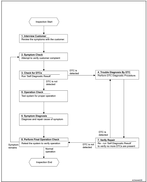
DETAILED FLOW
1.INTERVIEW CUSTOMER
Interview the customer to obtain as much information as possible about the conditions and environment under which the malfunction occurred.
>> GO TO 2.
2.SYMPTOM CHECK
Verify symptoms.
>> GO TO 3.
3.CHECK FOR DTCS
 With CONSULT
- Turn ignition switch ON.
- Select “Self Diagnostic Result” mode of “HVAC” using CONSULT.
- Check DTC.
Is any DTC detected? YES >> GO TO 4.
NO >> GO TO 5.
4.PERFORM DTC DIAGNOSTIC PROCEDURE
Perform the diagnostic procedure for the detected DTC. Refer to HAC-32, "DTC Inspection Priority Chart".
>> GO TO 7.
5.OPERATION CHECK
Perform the operation check. Refer to HAC-48, "Work Procedure".
>> GO TO 6.
6.SYMPTOM DIAGNOSIS
Check the symptom diagnosis table. Refer to HAC-96, "Diagnosis Chart By Symptom".
>> GO TO 8.
7.VERIFY REPAIR.
 With CONSULT
- Turn ignition switch ON.
- Select “Self Diagnostic Result” mode of “HVAC” using CONSULT.
- Check DTC.
Is any DTC detected? YES >> GO TO 4.
NO >> GO TO 8.
8.PERFORM FINAL OPERATION CHECK
Perform the operation check. Refer to HAC-48, "Work Procedure".
Does it operate normally? YES >> Inspection End.
NO >> GO TO 2.
OPERATION INSPECTION
Work Procedure
DESCRIPTION
The purpose of the operational check is to check that the individual system operates normally.
Conditions : Engine running at normal operating temperature
INSPECTION PROCEDURE
1.CHECK MEMORY FUNCTION
- Start the engine.
- Operate the temperature control switch (driver side) and raise the temperature setting to 32°C (90°F).
- Press the OFF switch.
- Turn the ignition switch OFF.
- Turn the ignition switch ON.
- Press the AUTO switch.
- Check that the temperature setting, before turning the ignition switch OFF, is stored.
Is the inspection result normal? YES >> GO TO 2.
NO >> Check power and ground circuits for A/C auto amp. Refer to HAC-56, "Diagnosis Procedure".
2.CHECK BLOWER MOTOR SPEED
- Operate the fan control dial. Check that the fan speed changes.
- Check the operation for all fan speeds.
Is the inspection result normal? YES >> GO TO 3.
NO >> Check blower motor system. Refer to HAC-85, "Diagnosis Procedure".
3.CHECK DISCHARGE AIR (MODE SWITCH AND DEF SWITCH)
- Press the MODE switch and the DEF switch.
- Check that the air outlets change according to each indicated air outlet by placing a hand in front of the outlets. Refer to HAC-10, "System Description".
NOTE:
Confirm that the A/C compressor clutch is engaged (sound or visual inspection)
and intake door position is at
FRE ( ) when the D/F (
 ) or DEF (
 )
is selected.
Is the inspection result normal?
YES >> GO TO 4.
)
is selected.
Is the inspection result normal?
YES >> GO TO 4.
NO >> Check mode door system. Refer to HAC-80, "Diagnosis Procedure".
4.CHECK INTAKE AIR
- Press the REC (
 )
switch. Indicator is turned ON.
)
switch. Indicator is turned ON. - Press the FRE ( )
switch. Indicator is turned ON.
- Listen for the intake door position change. (Slight change of blower sound can be heard.)
NOTE:
Confirm that the A/C compressor clutch is engaged (sound or visual inspection)
and the FRE ( ) switch is
pressed when the D/F ( ) or DEF (
 ) is selected.
Is the inspection result normal?
YES >> GO TO 5.
) is selected.
Is the inspection result normal?
YES >> GO TO 5.
NO >> Check intake door system. Refer to HAC-77, "Diagnosis Procedure".
5.CHECK A/C SWITCH
- Press the A/C switch.
- The A/C switch indicator is turned ON.
Confirm that the A/C compressor clutch engages (sound or visual inspection).
Is the inspection result normal? YES >> GO TO 6.
NO >> Check magnet clutch system. Refer to HAC-91, "Diagnosis Procedure".
6.CHECK TEMPERATURE DECREASE
- Operate the A/C compressor.
- Operate the temperature control dial (driver side) and lower the temperature setting to 18°C (60°F).
- Check that the cool air blows from the outlets.
Is the inspection result normal? YES >> GO TO 7.
NO >> Check for insufficient cooling. Refer to HAC-98, "Diagnosis Procedure".
7.CHECK TEMPERATURE INCREASE
- Operate the temperature control dial (driver side) and raise the temperature setting to 32°C (90°F) after warming up the engine.
- Check that the warm air blows from the outlets.
Is the inspection result normal? YES >> GO TO 8.
NO >> Check for insufficient heating. Refer to HAC-99, "Diagnosis Procedure".
8.CHECK DUAL MODE FUNCTION
- Press the DUAL mode switch, and then check that “DUAL” is shown on the display.
- Operate the temperature control dial (driver side). Check that the discharge air temperature (driver side) changes.
- Operate the temperature control dial (passenger side). Check that the discharge air temperature (passenger side) changes.
- Press the DUAL mode switch, and then check that the temperature setting (driver/passenger) is unified to the driver side temperature setting.
Is the inspection result normal? YES >> GO TO 9.
NO >> Refer to HAC-96, "Diagnosis Chart By Symptom" and perform the appropriate diagnosis.
9.CHECK AUTO MODE
- Press the AUTO switch, and then check that “AUTO” is shown on the display.
- Operate the temperature control dial (driver side). Check that the fan speed, outlet air or intake air changes. The discharge air temperature or fan speed varies depending on the ambient temperature, invehicle temperature, and temperature setting.
Is the inspection result normal? YES >> Inspection End.
NO >> Refer to HAC-96, "Diagnosis Chart By Symptom" and perform the appropriate diagnosis.
SYSTEM SETTING
Temperature Setting Trimmer
Description
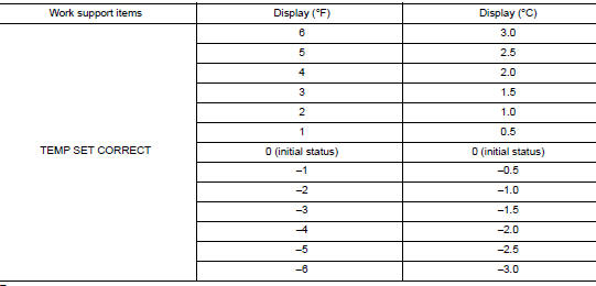
If the temperature felt by the customer is different than the airflow temperature controlled by the temperature setting, the auto amplifier control temperature can be adjusted to compensate for the temperature setting.
How to set
Using CONSULT, perform “TEMP SET CORRECT” in “WORK SUPPORT” of HVAC.
NOTE:
- When the temperature setting is set to 25.0°C (77°F) and −3.0°C (−6°F), the temperature controlled by auto amp is 25.0°C (77°F) − 3.0°C (6°F) = 22.0°C (71°F) and the temperature becomes lower than the temperature setting.
- When the battery cable is disconnected from the negative terminal or when the battery voltage becomes 10V or less, the setting of the difference between the temperature setting and control temperature may be cancelled.
Foot Position Setting Trimmer
DESCRIPTION
In FOOT mode, the air blowing to DEF can change ON/OFF.
HOW TO SET
 With CONSULT
Perform the “BLOW SET” of HVAC work support item.
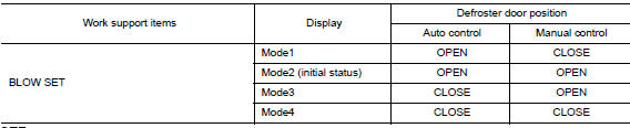
NOTE: When the battery cable is disconnected from the negative terminal or when the battery voltage becomes 10 V or less, the setting of the discharge air mix ratio in FOOT mode may be cancelled.
Inlet Port Memory Function (FRE)
Description
- If the ignition switch is turned to the OFF position while the FRE
(
 ) switch is set to ON
(fresh air intake),
“Perform the memory” or “Do not perform the memory” of the FRE (
) switch is set to ON
(fresh air intake),
“Perform the memory” or “Do not perform the memory” of the FRE ( ) switch ON (fresh air intake) condition
can be selected.
) switch ON (fresh air intake) condition
can be selected. - If “Perform the memory” was set, the FRE (
 ) switch will be ON (fresh
air intake) when turning the ignition
switch to the ON position again.
) switch will be ON (fresh
air intake) when turning the ignition
switch to the ON position again. - If “Do not perform the memory” was set, the air inlets will be controlled automatically when turning the ignition switch to the ON position again.
How to set
Using CONSULT, perform “FRE MEMORY SET” in “WORK SUPPORT” of HVAC.

NOTE: When the battery cable is disconnected from the negative terminal or when the battery voltage becomes 10V or less, the setting of the FRE switch memory function may be cancelled.
Inlet Port Memory Function (REC)
Description
- If the ignition switch is turned to the OFF position while the REC (
 ) switch is set to ON (recirculation),
“Perform the memory” or “Do not perform the memory” of the REC (
) switch is set to ON (recirculation),
“Perform the memory” or “Do not perform the memory” of the REC ( ) switch ON (recirculation) condition
can be selected.
) switch ON (recirculation) condition
can be selected. - If “Perform the memory” was set, the REC (
 ) switch will be ON (recirculation) when turning the ignition
switch to the ON position again.
) switch will be ON (recirculation) when turning the ignition
switch to the ON position again. - If “Do not perform the memory” was set, the air inlets will be controlled automatically when turning the ignition switch to the ON position again.
How to set
Using CONSULT, perform “REC MEMORY SET” in “WORK SUPPORT” of HVAC.

NOTE: When the battery cable is disconnected from the negative terminal or when the battery voltage becomes 10V or less, the setting of the REC switch memory function may be cancelled.
Target Evaporator Temp Upper Limit
DESCRIPTION
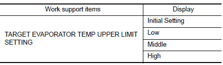
Set the target evaporator temperature upper limit.
HOW TO SET
 With CONSULT
Perform the “TARGET EVAPORATOR TEMP UPPER LIMIT SETTING” of HVAC work support item.
DOOR MOTOR STARTING POSITION RESET
Description
- Reset signal is transmitted from A/C auto amp. to air mix door motor, intake door motor and mode door motor. Starting position reset can be performed.
NOTE: During reset, DEF switch indicator blinks.
- When air mix door motor, intake door motor or mode door motor is removed and installed, always perform door motor starting position reset.
Work Procedure
1.PERFORM DOOR MOTOR STARTING POSITION RESET
With CONSULT
- Turn ignition switch ON.
- Select “Door Motor Starting Position Reset” in “ACTIVE TEST” mode of “HVAC” using CONSULT.
- Touch “Start” and wait a few seconds.
- Make sure the “COMPLETED” is displayed on CONSULT screen.
>> Inspection End.
 Wiring diagram
AUTOMATIC AIR CONDITIONING SYSTEM
Wiring Diagram
...
 DTC/circuit diagnosis
U1000 CAN COMM CIRCUIT
Description
CAN (Controller Area Network) is a serial communication system for real time
application. It is an on-vehicle
multiplex communication system with high data comm ...
Other materials:
Brake warning lamp
Component Function Check
1.CHECK BRAKE WARNING LAMP FUNCTION
Check that brake warning lamp in combination meter turns ON for 1 second
after ignition switch is turned ON.
CAUTION:
Never start the engine.
Is the inspection result normal?
YES >> GO TO 2.
NO >> Proceed to BRC-12 ...
Wiring diagram
SRS AIR BAG SYSTEM
Wiring Diagram
...
How to switch the display
With the ignition switch in the ON position, press
the CAMERA button or move the shift lever to the
R (Reverse) position to operate the Around View
Monitor.
The Around View Monitor displays different split
screen views depending on the position of the
shift lever. Press the CAMERA button to ...
