Nissan Rogue Service Manual: Front wiper motor HI circuit
Component Function Check
1.CHECK FRONT WIPER HI OPERATION
 CONSULT ACTIVE TEST
- Select FR WIPER of BCM (WIPER) active test item.
- Check front wiper operation.
HI : Front wiper (HI) operation
OFF : Front wiper OFF
Is the inspection result normal? YES >> Front wiper motor HI circuit is normal.
NO >> Refer to WW-38, "Diagnosis Procedure".
Diagnosis Procedure
Regarding Wiring Diagram information, refer to WW-22, "Wiring Diagram".
1. CHECK FRONT WIPER MOTOR FUSE
- Turn the ignition switch OFF.
- Check that the following fuse is not blown.

Is the fuse blown? YES >> Replace the fuse after repairing the affected circuit.
NO >> GO TO 2.
2. CHECK FRONT WIPER MOTOR (HI) OUTPUT VOLTAGE
- Turn the ignition switch ON.
- Select FR WIPER of BCM (WIPER) active test item.
- While performing the active test, check voltage between IPDM E/R harness connector and ground.
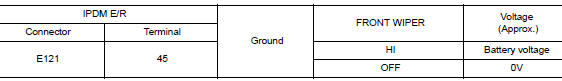
Is the inspection result normal? YES >> GO TO 3.
NO >> Replace IPDM E/R. Refer to PCS-35, "Removal and Installation".
3. CHECK FRONT WIPER MOTOR (HI) OPEN CIRCUIT
- Turn the ignition switch OFF.
- Disconnect IPDM E/R and front wiper motor.
- Check continuity between IPDM E/R harness connector and front wiper motor harness connector.
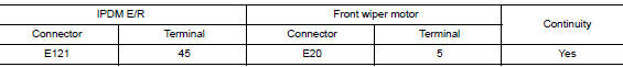
Is the inspection result normal? YES >> Replace front wiper motor. Refer to WW-67, "Removal and Installation".
NO >> Repair or replace harness.
 Front wiper motor lo circuit
Component Function Check
1.CHECK FRONT WIPER LO OPERATION
CONSULT ACTIVE TEST
Select FR WIPER of BCM (WIPER) active test item.
Check front wiper operation.
LO : Front wiper (LO ...
 Front wiper auto stop signal circuit
Component Function Check
1. CHECK FRONT WIPER (AUTO STOP) SIGNAL
Select FR WIPER STOP of BCM (WIPER) data monitor item.
Operate the front wiper.
Check that FR WIPER STOP cha ...
Other materials:
CAN system (type 5)
MAIN LINE BETWEEN IPDM-E AND DLC CIRCUIT
Diagnosis Procedure
1.CHECK CONNECTOR
Turn the ignition switch OFF.
Disconnect the battery cable from the negative terminal.
Check the following terminals and connectors for damage, bend and
loose connection (connector side
an ...
Cooling fan
Component Function Check
1.CHECK COOLING FAN FUNCTION
With CONSULT
Turn ignition switch ON.
Perform “COOLING FAN (DUAL)” in “ACTIVE TEST” mode of “IPDM E/R”
using CONSULT.
Touch “LOW”, “HI” on the CONSULT screen.
Check that cooling fan opera ...
B0094 crash zone sensor
DTC Logic
DTC DETECTION LOGIC
CONSULT name
DTC
DTC detecting condition
Repair order
CRASH ZONE SENSOR
[SENSOR FAIL]
B0094
Crash zone sensor has malfunctioned.
Refer to SRC-68, "Diagnosis Procedure".
CRASH ZONE SENSOR
[COMM ...
