Nissan Rogue Service Manual: P0643 sensor power supply
Description
ECM supplies a voltage of 5 V to some of the sensors systematically divided into 2 groups, respectively.
Accordingly, when a short circuit develops in a sensor power source, a malfunction may occur simultaneously in the sensors belonging to the same group as the short-circuited sensor.
Sensor power supply 1
- APP sensor 1
- CKP sensor (POS)
- Intake manifold runner control valve position sensor
- Refrigerant pressure sensor
- TP sensor
NOTE: If sensor power supply 1 circuit is malfunctioning, DTC P0643 is displayed.
Sensor power supply 2
- APP sensor 2
- CMP sensor (PHASE)
- EVT control position sensor
- EOP sensor
- MAF sensor
DTC Description
DTC DETECTION LOGIC
| DTC No. | CONSULT screen terms (Trouble diagnosis content) | DTC detecting condition |
| P0643 | SENSOR POWER/CIRC (Sensor reference voltage ″A″ circuit high) | ECM detects that the voltage of sensor power supply 1 is excessively low or high. |
POSSIBLE CAUSE
- Harness or connectors
- APP sensor 1 circuit is shorted.
- CKP sensor (POS) circuit is shorted.
- Intake manifold runner control valve position sensor circuit is shorted.
- TP sensor circuit is shorted.
- Refrigerant pressure sensor circuit is shorted.
- Accelerator pedal position sensor
- CKP sensor (POS)
- Intake manifold runner control valve position sensor
- Throttle position sensor
- Refrigerant pressure sensor
FAIL-SAFE
ECM stops the electric throttle control actuator control, throttle valve is maintained at a fixed opening (approx.
5 degrees) by the return spring.
DTC CONFIRMATION PROCEDURE
1.PRECONDITIONING
If DTC Confirmation Procedure has been previously conducted, always perform the following procedure before conducting the next test.
- Turn ignition switch OFF and wait at least 10 seconds.
- Turn ignition switch ON.
- Turn ignition switch OFF and wait at least 10 seconds.
TESTING CONDITION: Before performing the following procedure, confirm that battery voltage is more than 10 V at idle.
>> GO TO 2.
2.PERFORM DTC CONFIRMATION PROCEDURE
- Start engine and let it idle for 1 second.
- Check DTC.
Is DTC detected? YES >> Refer to EC-380, "Diagnosis Procedure".
NO >> INSPECTION END
Diagnosis Procedure
1.CHECK GROUND CONNECTION
- Turn ignition switch OFF.
- Check ground connection E9 and E15. Refer to Ground Inspection in GI-44, "Circuit Inspection".
Is the inspection result normal? YES >> GO TO 2.
NO >> Repair or replace ground connection.
2.CHECK ACCELERATOR PEDAL POSITION SENSOR 1 POWER SUPPLY CIRCUIT
- Disconnect accelerator pedal position (APP) sensor harness connector.
- Turn ignition switch ON.
- Check the voltage between APP sensor harness connector and ground.
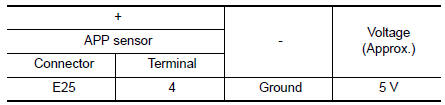
Is the inspection result normal? YES >> GO TO 5.
NO >> GO TO 3.
3.CHECK SENSOR POWER SUPPLY CIRCUITS
Check harness for short to power and short to ground, between the following terminals.

Is the inspection result normal? YES >> GO TO 4.
NO >> Repair short to ground or short to power in harness or connectors.
4.CHECK COMPONENTS
Check the following.
- Crankshaft position sensor (POS) (Refer to EC-297, "Component Inspection (Crankshaft Position sensor)".)
- Intake manifold runner control valve position sensor (Refer to EC-424, "Diagnosis Procedure".)
- Refrigerant pressure sensor (Refer to EC-482, "Diagnosis Procedure".)
- TP sensor (Refer to EC-218, "Component Inspection".)
Is the inspection result normal? YES >> GO TO 5.
NO >> Repair or replace malfunctioning component.
5.CHECK APP SENSOR
Refer to EC-442, "Component Inspection".
Is the inspection result normal? YES >> GO TO 6.
NO >> Replace accelerator pedal assembly. Refer to ACC-3, "Removal and Installation".
6.CHECK INTERMITTENT INCIDENT
Refer to GI-41, "Intermittent Incident".
>> INSPECTION END
 P060B ECM
DTC Description
DTC DETECTION LOGIC
DTC No.
CONSULT screen terms
(Trouble diagnosis content)
DTC detecting condition
P060B
CONTROL MODULE
(Internal control module A/D ...
 P0850 PNP switch
Description
Transmission range switch is turn ON when the selector lever is P or N.
ECM detects the position because the continuity of the line (the ON) exists.
DTC Description
DTC DETECTION LOG ...
Other materials:
Rear window defogger power supply and ground circuit
Description
Heats the heating wire with the power supply from the rear window defogger
relay to prevent the rear window
from fogging up.
Component Function Check
1. CHECK REAR WINDOW DEFOGGER
Check that the heating wire of rear window defogger is heated when turning
the rear window defogger ...
Key interlock cable
Exploded View
Key cylinder
Clip
Key interlock cable
Shift selector assembly
Removal and Installation
REMOVAL
CAUTION:
Always apply the parking brake before performing removal and installation.
Move shift selector to the “N” position.
Remo ...
Symptom diagnosis
AUDIO SYSTEM
Symptom Table
RELATED TO AUDIO
Symptoms
Check items
Probable malfunction location
The disk cannot be removed
Audio unit
Malfunction in audio unit.
Refer to AV-18, "On Board Diagnosis Function".
No sound comes out or the le ...
