Nissan Rogue Service Manual: Front wiper auto stop signal circuit
Component Function Check
1. CHECK FRONT WIPER (AUTO STOP) SIGNAL
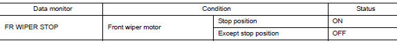
- Select FR WIPER STOP of BCM (WIPER) data monitor item.
- Operate the front wiper.
- Check that FR WIPER STOP changes from ON to OFF according to the wiper position
Is the inspection result normal? YES >> Front wiper auto stop signal circuit is normal.
NO >> Refer to WW-40, "Diagnosis Procedure".
Diagnosis Procedure
Regarding Wiring Diagram information, refer to WW-22, "Wiring Diagram".
1. CHECK FRONT WIPER MOTOR (AUTO STOP) OUTPUT VOLTAGE
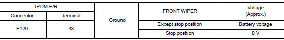
- Turn the ignition switch ON.
- Check voltage between IPDM E/R harness connector and ground.
Is the inspection result normal? YES >> Check for intermittent failure.
NO >> GO TO 2.
2. CHECK FRONT WIPER MOTOR (AUTO STOP) SHORT CIRCUIT
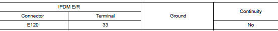
- Turn the ignition switch OFF.
- Disconnect IPDM E/R and front wiper motor.
- Check continuity between IPDM E/R harness connector and ground.
Is the inspection result normal? YES >> Repair or replace harness.
NO >> GO TO 3.
3. CHECK FRONT WIPER MOTOR (AUTO STOP) CIRCUIT CONTINUITY
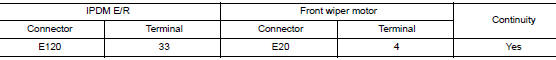
Check continuity between IPDM E/R harness connector and front wiper motor harness connector.
Is the inspection result normal?
YES >> Replace front wiper motor. Refer to WW-67, "Removal and Installation".
NO >> Repair or replace harness.
 Front wiper motor HI circuit
Component Function Check
1.CHECK FRONT WIPER HI OPERATION
CONSULT ACTIVE TEST
Select FR WIPER of BCM (WIPER) active test item.
Check front wiper operation.
HI : Front wiper (HI ...
 Front wiper motor ground circuit
Diagnosis Procedure
Regarding Wiring Diagram information, refer to WW-22, "Wiring Diagram".
1. CHECK FRONT WIPER MOTOR GROUND CIRCUIT
Turn the ignition switch OFF.
Discon ...
Other materials:
Basic inspection
INSPECTION AND ADJUSTMENT
ADDITIONAL SERVICE WHEN REPLACING CONTROL UNIT (BCM)
ADDITIONAL SERVICE WHEN REPLACING CONTROL UNIT (BCM) : Description
BEFORE REPLACEMENT
When replacing BCM, save or print current vehicle specification with CONSULT
configuration before replacement.
NOTE:
If “Befo ...
Ignition coil
Exploded View
Ignition coil
Spark plug
Rocker cover
Removal and Installation
REMOVAL
Remove air duct assembly. Refer to EM-24, "Exploded View" .
Disconnect the harness connector from the ignition coil.
Remove the ignition coil.
CAUTION:
...
BSW system operation
BSW system operation
The BSW system operates above approximately
20 MPH (32 km/h).
When the camera unit detects vehicles in the
detection zone, the Blind Spot indicator light
located inside the outside mirrors will illuminate. If
the turn signal is then activated, the system
chimes (twi ...
