Nissan Rogue Service Manual: Encoder circuit
Description
Detects condition of the front power window motor LH operation and transmits to main power window and door lock/unlock switch as pulse signal.
Component Function Check
1.CHECK ENCODER OPERATION
Check front driver side door glass perform AUTO open/close operation normally when main power window and door lock/unlock switch.
Is the inspection result normal? YES >> Encoder operation is OK.
NO >> Refer to PWC-45, "Diagnosis Procedure"
Diagnosis Procedure
Encoder Circuit Check
1.CHECK ENCODER OPERATION
- Turn ignition switch ON.
- Check signal between main power window and door lock/unlock switch harness connector and ground with oscilloscope.
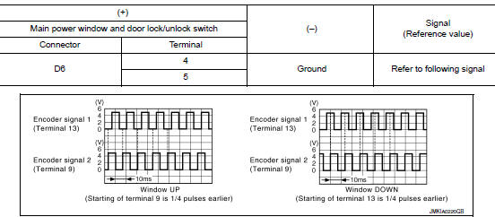
Is the inspection result normal? YES >> GO TO 7.
NO >> GO TO 2.
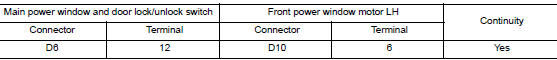
2.CHECK ENCORDER SIGNAL CIRCUIT
- Turn ignition switch OFF.
- Disconnect main power window and door lock/unlock switch connector and front power window motor LH connector.
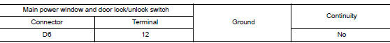
- Check continuity between main power window and door lock/unlock switch harness connector and front power window motor LH harness connector.
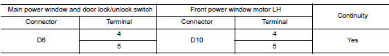
- Check continuity between main power window and door lock/unlock switch harness connector and ground.
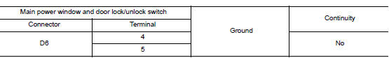
Is the inspection result normal? YES >> GO TO 3.
NO >> Repair or replace harness.
3.CHECK ENCORDER POWER SUPPLY CIRCUIT
- Connect main power window and door lock/unlock switch connector.
- Turn ignition switch ON.
- Check voltage between front power window motor LH harness connector and ground.
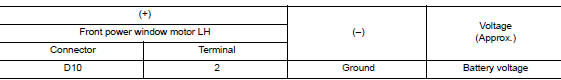
Is the inspection result normal? YES >> GO TO 4.
NO >> GO TO 5.
4.CHECK GROUND CIRCUIT
- Turn ignition switch OFF.
- Check continuity between front power window motor LH harness connector and ground.
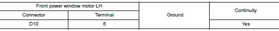
Is the inspection result normal? YES >> GO TO 7.
NO >> GO TO 6.
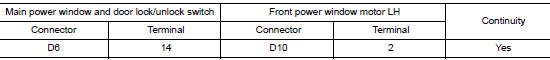
5.CHECK HARNESS CONTINUITY 1
- Turn ignition switch OFF.
- Check continuity between main power window and door lock/unlock switch harness connector and front power window motor LH harness connector.
- Check continuity between main power window and door lock/unlock switch harness connector and ground.
Is the inspection result normal? YES >> Replace main power window and door lock/unlock switch. Refer to PWC-65, "Removal and Installation".
NO >> Repair or replace harness.
6.CHECK HARNESS CONTINUITY 2
- Disconnect main power window and door lock/unlock switch connector.
- Check continuity between main power window and door lock/unlock switch harness connector and front power window motor LH harness connector.
Is the inspection result normal? YES >> Replace main power window and door lock/unlock switch. Refer to PWC-65, "Removal and Installation".
NO >> Repair or replace harness.
7.CHECK INTERMITTENT INCIDENT
Refer to GI-41, "Intermittent Incident".
>> Inspection End.
 Power window motor
DRIVER SIDE
DRIVER SIDE : Description
Door glass moves UP/DOWN by receiving the signal from main power window and
door lock/unlock switch.
DRIVER SIDE : Component Function Check
1. CHECK FRONT P ...
 Power window relay
Description
Power is supplied to the main power window and door lock/unlock with BCM
control.
Component Function Check
1. CHECK POWER WINDOW RELAY POWER SUPPLY CIRCUIT
Check that an operation no ...
Other materials:
Driving the vehicle
CONTINUOUSLY VARIABLE
TRANSMISSION (CVT)
The Continuously Variable Transmission (CVT) in
your vehicle is electronically controlled to produce
maximum power and smooth operation.
The recommended operating procedures for this
transmission are shown on the following pages.
Follow these proce ...
Regulatory Information
FCC Regulatory information
CAUTION: To maintain compliance with
FCC’s RF exposure guidelines, use only the
supplied antenna. Unauthorized antenna,
modification, or attachments could damage
the transmitter and may violate FCC regulations.
Operation is subject to the follow ...
Spark plug
Exploded view
Ignition coil
Spark plug
Rocker cover
Removal and installation
REMOVAL
Remove air duct assembly.
Remove ignition coil. Refer to EM-36, "Exploded View".
Remove spark plug using Tool.
Tool number : — (J-48891)
INSPECT ...
