Nissan Rogue Service Manual: Condenser
Exploded View
- Air guide (LH)
- Condenser upper bracket (LH)
- Condenser (includes liquid tank)
- Condenser upper bracket (RH)
- Air guide (RH)
- Refrigerant pressure sensor
- Condenser lower bracket (RH)
- Condenser lower bracket (LH)
CONDENSER
CONDENSER : Removal and Installation
REMOVAL
CAUTION: Before servicing, turn the ignition switch off, disconnect both battery cables and wait at least three minutes.
- Disconnect the negative and positive battle terminals and wait at least three minutes. Refer to PG-75, "Removal and Installation (Battery)".
- Discharge the refrigerant. Refer to HA-23, "Recycle Refrigerant".
- Remove front air duct. Refer to EM-24, "Removal and Installation".
- Remove front bumper fascia. Refer to EXT-17, "Removal and Installation".
- Remove front combination lamp (RH). Refer to EXL-119, "Removal and Installation".
- Remove air guides (LH/RH). Refer to HA-37, "Exploded View".
- Remove crash zone sensor. Refer to SR-22, "Removal and Installation".
- Disconnect the harness connector from the refrigerant pressure sensor.
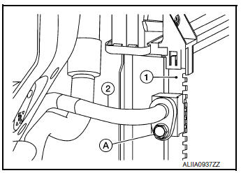
- Remove the bolt (A) that retains the high-pressure flexible hose (2) to the condenser (1).
CAUTION: Cap or wrap the joint of the pipe with suitable material such as vinyl tape to avoid the entry of air.
- Remove bolt (A) that retains high-pressure pipe (1) to condenser (2).
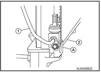
- Remove the condenser bracket bolts and condenser.
INSTALLATION
Installation is in the reverse order of removal.
CAUTION:
- Tighten bolts to specification. Refer to HA-32, "Exploded View".
- Do not reuse O-rings.
- Apply A/C oil to new O-rings for installation.
- After charging the refrigerant, check for leaks. Refer to HA-21, "Leak Test".
LIQUID TANK
LIQUID TANK : Removal and Installation
The liquid tank is serviced as an assembly with the condenser. Refer to HA-37, "CONDENSER : Removal and Installation".
REFRIGERANT PRESSURE SENSOR
REFRIGERANT PRESSURE SENSOR : Removal and Installation
REMOVAL
- Discharge the refrigerant. Refer to HA-23, "Recycle Refrigerant".
- Remove front air duct. Refer to EM-24, "Removal and Installation".
- Remove front bumper fascia. Refer to EXT-17, "Removal and Installation".
- Remove air guide (RH). Refer to HA-37, "Exploded View".
- Disconnect the harness connector from the refrigerant pressure sensor and remove.
CAUTION: Cap or wrap the opening of the refrigerant pressure sensor with suitable material such as vinyl tape to avoid the entry of air.
INSTALLATION
Installation is in the reverse order of removal.
CAUTION:
- Do not reuse O-ring.
- Apply A/C oil to new O-rings for installation.
- After charging the refrigerant, check for leaks. Refer to HA-21, "Leak Test".
 Cooler pipe and hose
Exploded View
Condenser
High-pressure flexible hose
Low-pressure flexible hose
Low-pressure pipe
Heating and cooling unit assembly
High-pressure pipe
Compressor
...
 Heating and cooling unit assembly
Exploded View
Steering Member
Heating and cooling unit assembly
Steering member
Bolt
Nut
Automatic Air Conditioning
Wiring harness
Air mix door duct (LH)
...
Other materials:
Service data and specifications (SDS)
BODY ALIGNMENT
Body Center Marks
mark has been placed on each part of the body to indicate the vehicle center.
When repairing parts damaged
by an accident which might affect the vehicle frame (members, pillars, etc.),
more accurate and effective
repair will be possible by using these marks t ...
Structure and operation
TRANSAXLE
TRANSAXLE : Cross-Sectional View
Converter housing
Oil pump
Planetary gear
Control valve
Oil pan
Steel belt
Primary pulley
Secondary pulley
Side cover
Transaxle case
Differential case
Final gear
Reduction gear
Idler gear
Output gear
Drive sp ...
Symptom diagnosis
COMBINATION SWITCH SYSTEM SYMPTOMS
Symptom Table
Perform the data monitor of CONSULT to check for any malfunctioning
item.
Check the malfunction combinations.
Identify the malfunctioning part from the agreed combination and repair
or replace the part.
NORMAL OPERA ...
