Nissan Rogue Service Manual: ECU diagnosis information
CHASSIS CONTROL MODULE
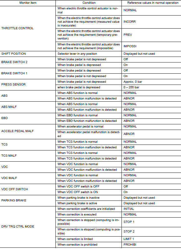
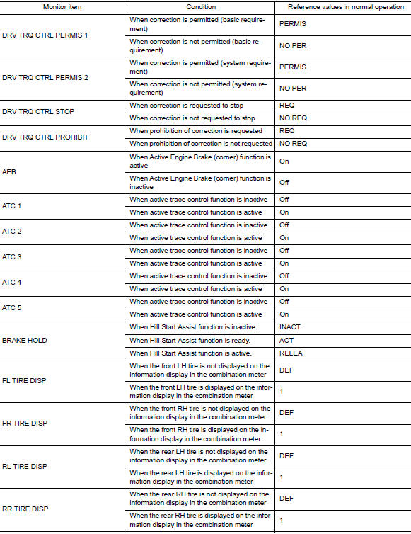
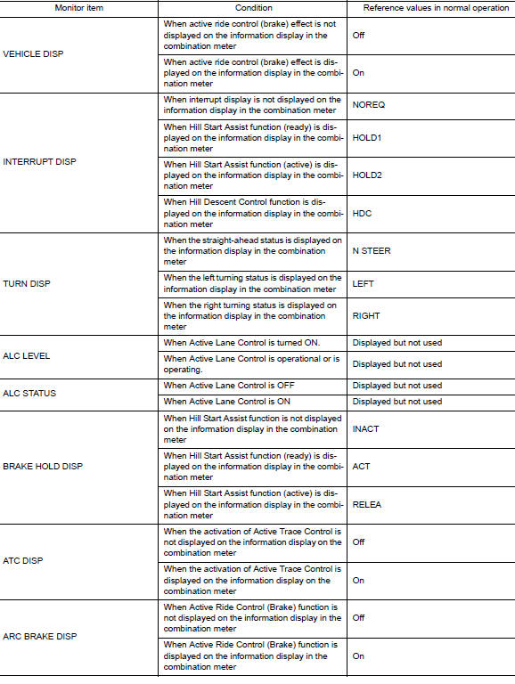
Reference Value
CONSULT DATA MONITOR STANDARD VALUE
NOTE: The following table includes information (items) inapplicable to this vehicle. For information (items) applicable to this vehicle, refer to CONSULT display items.
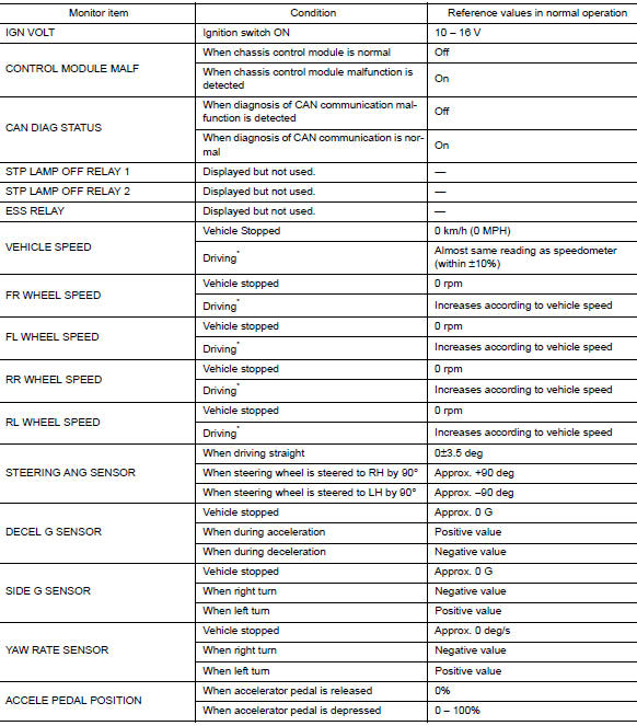
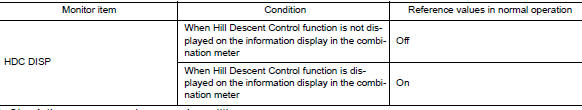
*: Check tire pressure under normal conditions.
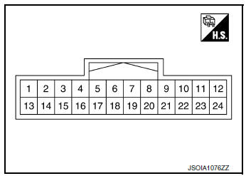
TERMINAL LAYOUT
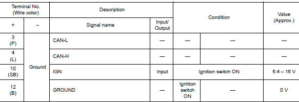
PHYSICAL VALUES
Fail-Safe (Chassis Control Module)
When a malfunction occurs in the chassis control module, the master warning lamp turns ON and an interrupt is displayed on the information display of the combination meter.
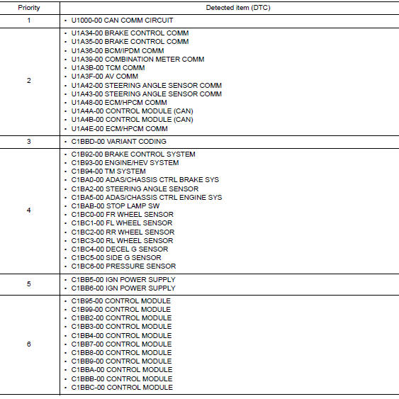
DTC Inspection Priority Chart
When multiple DTCs are displayed simultaneously, check them one by one according to the following priority list.
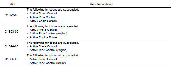
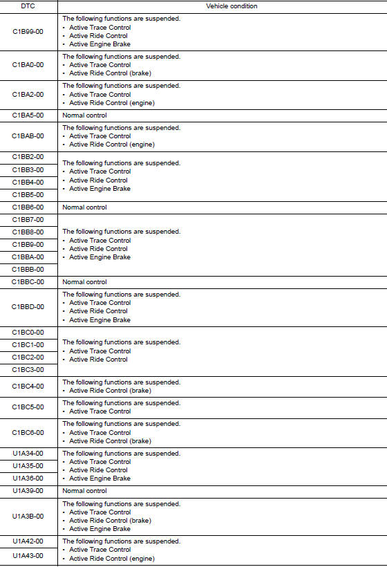
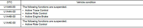
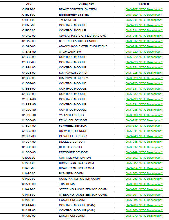
DTC Index
 System description
COMPONENT PARTS
Component Parts Location
Front of vehicle
Instrument panel LH
View with glove box removed
Rear of engine compartment RH
RH front of vehicle
Front of engine compar ...
 Wiring diagram
CHASSIS CONTROL
Wiring Diagram
...
Other materials:
How to use the remote keyless entry
function
The remote keyless entry function can operate all
door locks using the remote keyless function of
the Intelligent Key. The remote keyless function
can operate at a distance of 33 ft (10 m) away
from the vehicle. The operating distance depends
upon the conditions around the vehicle.
The remot ...
ECU diagnosis information
AWD CONTROL UNIT
Reference Value
VALUES ON THE DIAGNOSIS TOOL
NOTE:
The following table includes information (items) inapplicable to this vehicle.
For information (items) applicable
to this vehicle, refer to CONSULT display items.
*: The values are changed by throttle opening and eng ...
Liftgate release
WARNING
Always be sure the liftgate has been
closed securely to prevent it from opening
while driving.
Do not drive with the liftgate open. This
could allow dangerous exhaust gases
to be drawn into the vehicle. For additional
information, refer to “Ex ...
