Nissan Rogue Service Manual: ECU diagnosis information
FRONT AIR CONTROL
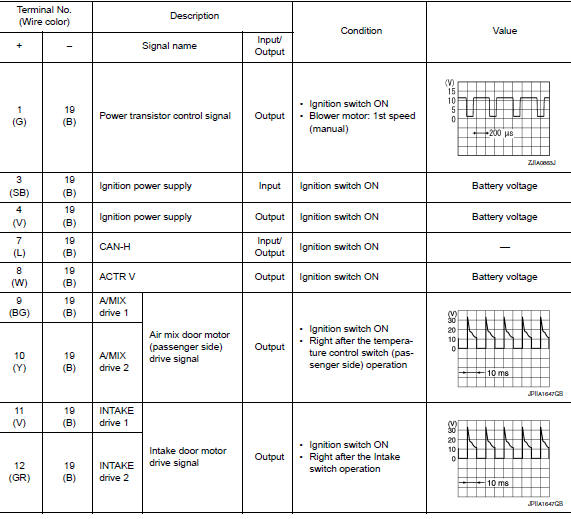
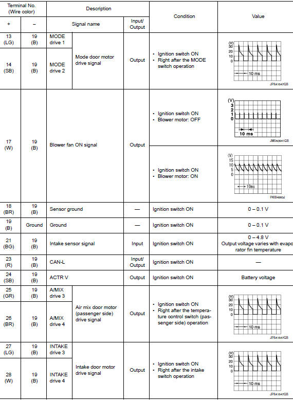
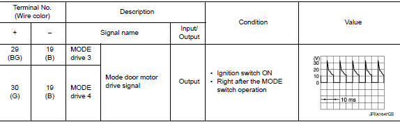
Reference Value
TERMINAL LAYOUT
PHYSICAL VALUES
DTC Inspection Priority Chart
If some DTCs are displayed at the same time, perform inspections one by one based on the following priority chart.
|
Priority |
Detected items (DTC) |
| 1 |
|
| 2 |
|
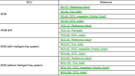
DTC Index

ECM, IPDM E/R, BCM
List of ECU Reference
 System description
COMPONENT PARTS
Component Part Location
RH side of engine compartment
RH front of vehicle (view with front
bumper fascia removed)
No.
Component
Description
...
 Wiring diagram
MANUAL AIR CONDITIONING SYSTEM
Wiring Diagram
...
Other materials:
Voice commands
Voice commands can be used to operate the
Bluetooth® Hands-Free Phone System. Press
the button and say “Phone” to
bring up the
phone command menu. The available options
are:
Call
Phonebook
Recent Calls
Messaging (if available)
Show Applications ( ...
Seat belt extenders
3rd row shown; 2nd row similar
Seat belt hook
When the seat belt is not in use and when folding
down the rear seats, hook the rear seat belts on
the seat belt hooks.
If, because of body size or driving position, it is
not possible to properly fit the lap/shoulder belt
and fasten it, an ex ...
U0100 lost communication (ECM A)
DTC Description
DTC DETECTION LOGIC
DTC
CONSULT screen terms
(Trouble diagnosis content)
DTC detection condition
U0100
LOST COMM (ECM A)
(Lost Communication With ECM/PCM A)
When the ignition switch is ON, TCM is unable to receive the CAN
communications signal f ...
