Nissan Rogue Service Manual: Disassembly and assembly
FUEL LEVEL SENSOR UNIT
Exploded View
Fuel Level Sensor Unit
- Fuel filter and pump assembly
- Fuel level sensor unit
- Float arm assembly
- Fuel tank temperature sensor
Disassembly and Assembly
NOTE: Fuel level sensor unit and fuel tank temperature sensor are replaced as and assembly.
DISASSEMBLY
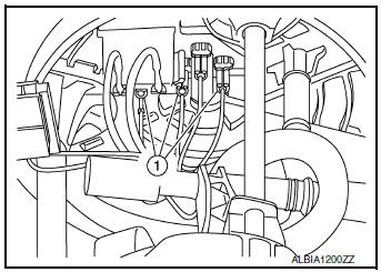
- Disconnect fuel level sensor unit/fuel tank temperature sensor harness connector (1).
NOTE: Hold connector with your fingers, because there is no tab for releasing stopper. Pull harness connector straight downward.
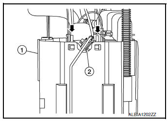
- Remove fuel tank temperature sensor (2) from fuel filter and fuel pump assembly (1).
- Using a suitable tool press up on clip (
 ) and remove fuel level
sensor unit (2) from fuel filter and fuel pump assembly (1).
) and remove fuel level
sensor unit (2) from fuel filter and fuel pump assembly (1).
CAUTION:
- Be careful not to damage the fuel level sensor unit.
- Do not disassemble fuel filter and fuel pump assembly.
ASSEMBLY
- Slide fuel level sensor unit (1) until it aligns to installation groove (A).
- After inserting, apply force in reverse direction (removal direction) to ensure it cannot be pulled out.
- Connect fuel level sensor unit/fuel tank temperature sensor harness connectors (1).
- Check fuel level sensor unit installation position to fuel filter and pump assembly for damage. Replace as necessary.
- Assembly of remaining components is in the reverse order of disassembly.
INSPECTION AFTER INSTALLATION
Use the following procedure to check for fuel leaks.
- Turn ignition switch “ON” (with engine stopped), then check connections for leaks by applying fuel pressure to fuel piping.
- Start engine and let it idle and check there are no fuel leaks at the fuel system connections.
SERVICE DATA AND SPECIFICATIONS (SDS)
Fuel Tank
Standard and Limit
| Fuel tank capacity | Approx. 55  ( 14-1/2
US gal, 12-1/8 Imp gal) ( 14-1/2
US gal, 12-1/8 Imp gal) |
| Fuel recommendation | Refer to MA-11 |
 EVAP canister filter
Exploded View
EVAP canister vent control valve hose
Canister drain hose
Plug
EVAP canister filter
Front
Removal and Installation
REMOVAL
Disconnect EVAP canister ...
 Exhaust System
...
Other materials:
Basic inspection
DIAGNOSIS AND REPAIR WORK FLOW
Work Flow
DETAILED FLOW
1.INTERVIEW FROM THE CUSTOMER
Clarify customer complaints before inspection. First of all, perform an
interview utilizing DLN-32, "Diagnostic
Work Sheet" and reproduce symptoms as well as fully understand it. Ask customer
abou ...
Steering wheel
Exploded View
Steering wheel
Removal and Installation
REMOVAL
Set the front wheels and tires in the straight-ahead position.
Remove driver air bag module. Refer to SR-12, "Removal and
Installation"
Remove steering wheel bolt.
Disconnect harn ...
B terminal circuit
Description
Terminal “B” is constantly supplied with battery power.
Diagnosis Procedure
Regarding Wiring Diagram information, refer to STR-7, "Wiring Diagram".
CAUTION:
Perform diagnosis under the condition that the engine cannot start by the
following procedure.
Remov ...
