Nissan Rogue Service Manual: Cooler pipe and hose
Exploded View
- Condenser
- High-pressure flexible hose
- Low-pressure flexible hose
- Low-pressure pipe
- Heating and cooling unit assembly
- High-pressure pipe
- Compressor
- O-ring
- Low-pressure service port
- High-pressure service port
LOW-PRESSURE PIP
LOW-PRESSURE PIPE : Removal and Installation
REMOVAL
- Discharge the refrigerant. Refer to HA-23, "Recycle Refrigerant".
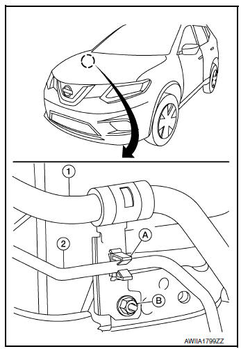
- Remove bolts (A) and engine upper mount (1).
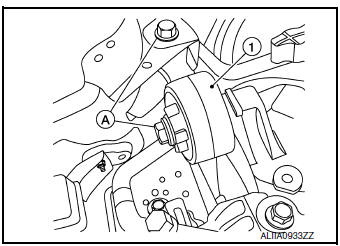
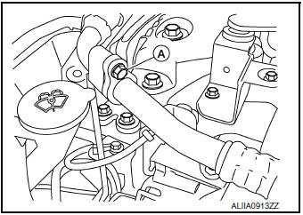
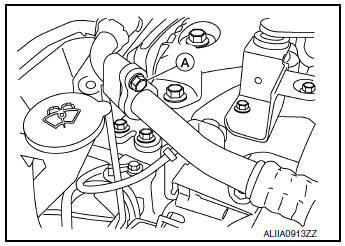
- Remove the bolt (A) that retains the low-pressure flexible hose to the low-pressure pipe.
CAUTION: Cap or wrap the joint of the pipe with suitable material such as vinyl tape to avoid the entry of air.
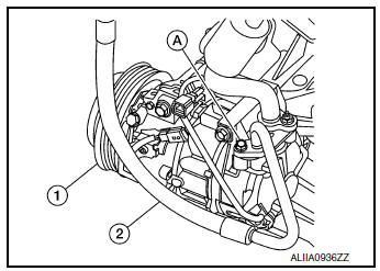
- Remove low-pressure pipe bracket bolts (A) and bracket.
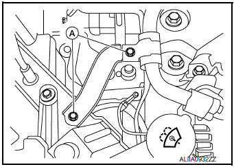
- Release high-pressure pipe (2) from clamp (A).
- Remove nut (B) and low-pressure pipe (1).

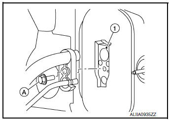
- Remove the bolt (A) that retains the low-pressure and high-pressure pipe to the expansion valve (1).
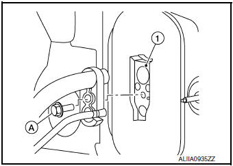
- Remove low-pressure pipe.
INSTALLATION
Installation is in the reverse order of removal.
CAUTION:
- Tighten bolts to specified torque. Refer to HA-32, "Exploded View".
- Do not reuse O-rings.
- Apply A/C oil to new O-rings for installation.
- After charging refrigerant, check for leaks. Refer to HA-21, "Leak Test".
LOW-PRESSURE FLEXIBLE HOSE
LOW-PRESSURE FLEXIBLE HOSE : Removal and Installation
REMOVAL
- Discharge the refrigerant. Refer to HA-23, "Recycle Refrigerant".
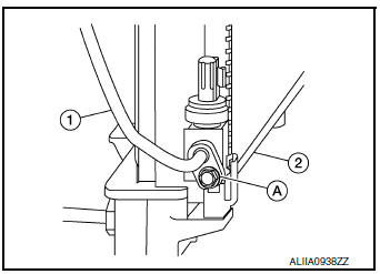
- Remove the bolt (A) that retains the low-pressure flexible hose to the low-pressure pipe.
CAUTION: Cap or wrap the joint of the pipe with suitable material such as vinyl tape to avoid the entry of air.
- Remove the nut (A) that retains the low-pressure flexible hose to the compressor.
- Remove the low-pressure flexible hose.
INSTALLATION
Installation is in the reverse order of removal.
CAUTION:
- Tighten nut/bolt to specified torque. Refer to HA-32, "Exploded View".
- Do not reuse O-rings.
- Apply A/C oil to new O-rings for installation.
- After charging refrigerant, check for leaks. Refer to HA-21, "Leak Test".
HIGH-PRESSURE PIPE
HIGH-PRESSURE PIPE : Removal and Installation
REMOVAL
- Discharge the refrigerant. Refer to HA-23, "Recycle Refrigerant".
- Remove front bumper fascia. Refer to EXT-17, "Removal and Installation".
- Remove air duct assembly. Refer to EM-24, "Exploded View".
- Remove bolts (A) and upper engine mount (1).
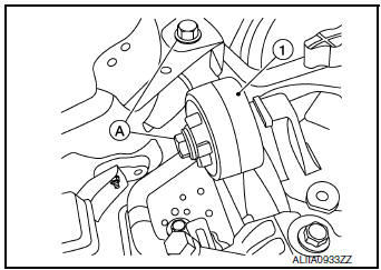
- Release high-pressure pipe (2) from clamp (A).
(1): Low-pressure pipe
(B): Nut
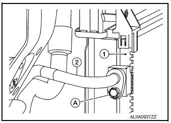
- Remove bolt (A) that retains high-pressure pipe (1) to the condenser
(2).
CAUTION: Cap or wrap the joint of the pipe with suitable material such as vinyl tape to avoid the entry of air.
- Remove the bolt (A) that retains the high-pressure and low-pressure pipe to the expansion valve (1).
- Remove high-pressure pipe.
INSTALLATION
Installation is in the reverse order of removal.
CAUTION:
- Tighten bolts to specified torque. Refer to HA-32, "Exploded View".
- Do not reuse O-rings.
- Apply A/C oil to new O-rings for installation.
- After charging the refrigerant, check for leaks. Refer to HA-21, "Leak Test".
HIGH-PRESSURE FLEXIBLE HOSE
HIGH-PRESSURE FLEXIBLE HOSE : Removal and Installation
REMOVAL
- Discharge the refrigerant. Refer to HA-23, "Recycle Refrigerant".
- Remove front bumper fascia. Refer to EXT-17, "Removal and Installation".
- Remove the bolt (A) that retains the high-pressure flexible hose (2) to the condenser (1).
CAUTION: Cap or wrap the joint of the pipe with suitable material such as vinyl tape to avoid the entry of air.
- Remove the bolt (A) that retains the high-pressure flexible hose (2) to the compressor (1).
INSTALLATION
Installation is in the reverse order of removal.
CAUTION:
- Tighten bolts to specified torque. Refer to HA-37, "Exploded View".
- Do not reuse O-rings.
- Apply A/C oil to new O-rings for installation.
- After charging the refrigerant, check for leaks. Refer to HA-21, "Leak Test".
 Compressor
Exploded View
Compressor
Removal and Installation
REMOVAL
Discharge the refrigerant. Refer to HA-23, "Recycle Refrigerant".
Remove the engine under cover. Refer to EX ...
 Condenser
Exploded View
Air guide (LH)
Condenser upper bracket (LH)
Condenser (includes liquid tank)
Condenser upper bracket (RH)
Air guide (RH)
Refrigerant pressure sensor
C ...
Other materials:
Symptom diagnosis
CVT CONTROL SYSTEM
Symptom Table
The diagnosis item number indicates the order of check. Start checking
in the order from 1.
Perform diagnoses of symptom table 1 before symptom table 2.
Symptom Table 1
Symptom Table 2
...
Diagnosis and repair work flow
Work Flow
NOTE:
The Signal Tech II Tool [- (J-50190)] can be used to perform the following
functions. Refer to the Signal Tech II
User Guide for additional information.
Activate and display TPMS sensor IDs
Display tire pressure reported by the TPMS sensor
Read TPMS DTC ...
P0863 TCM communication
DTC Description
DTC DETECTION LOGIC
DTC
CONSULT screen terms
(Trouble diagnosis content)
DTC detection condition
P0863
CONTROL UNIT (CAN)
(TCM Communication Circuit)
An error is detected at the initial CAN diagnosis of TCM.
POSSIBLE CAUSE
TCM
FAIL-SAFE
...
