Nissan Rogue Service Manual: Component parts
Component Parts Location
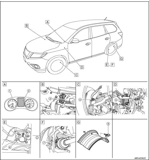
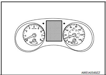
- Combination meter
- Engine room (LH)
- Left front wheel assembly
- Behind instrument panel (LH)
- Left rear wheel assembly
- Left rear wheel assembly
- Wheel
| No. | Component parts | Function |
| 1 | Combination meter | The combination meter receives tire pressure status from the BCM via CAN communication. The combination meter will display the low tire pressure warning lamp when a low tire pressure or system malfunction is detected by the BCM. |
| 2 | Information display (in combination meter) | Refer to WT-7, "Information Display". |
| 3 | ABS actuator and electric unit (control unit) | Mainly transmits the following signals to BCM via CAN communication
|
| 4 | Front wheel sensor LH | Refer to BRC-10, "Wheel Sensor and Sensor Rotor". |
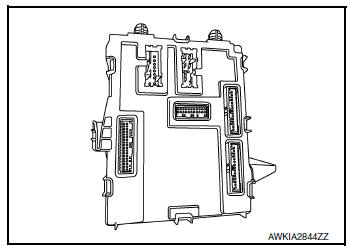
| 5 | BCM | Refer to WT-7, "BCM". |
| 6 | Rear wheel sensor LH | Refer to BRC-10, "Wheel Sensor and Sensor Rotor". |
| 7 | Rear wheel sensor LH (with AWD) | Refer to BRC-10, "Wheel Sensor and Sensor Rotor". |
| 8 | Tire pressure sensor | Refer to WT-7, "Tire Pressure Sensor". |
BCM
The BCM reads the air pressure signal received by the remote keyless entry receiver (without Intelligent Key System) or intelligent key receiver (with Intelligent Key System). In addition, the BCM also uses the outside key antennas (driver side, passenger side and rear bumper) to identify the location of the tire pressure sensors. The BCM has a self-diagnosis function used to detect system malfunctions.
Information Display
A low tire pressure warning or flat tire warning is shown on the vehicle information display when they are transmitted from BCM to combination meter via CAN communication.
| Condition | Vehicle information displ | |
| Ignition switch OFF | Not indicated | |
| Ignition switch ON | Low tire pressure warning lamp remains ON after blinking for one minute. [Tire Pressure Monitoring System (TPMS) malfunction.] | Not indicated |
| Ignition switch ON | Low tire pressure warning lamp remains ON. (low tire pressure) | Indicated |
| Ignition switch ON | Flat tire warning | Indicated |
Tire Pressure Sensor
The tire pressure sensor (1) integrated with a valve is installed on a wheel (2), and transmits a detected air pressure and temperature signal by radio wave.
 : Outside

 System
System Description
When the vehicle has reached a speed of 40 km/h (25 MPH) or greater, the BCM
receives a signal transmitted
from the tire pressure sensors installed in each wheel. If the BCM det ...
Other materials:
System description
VENTILATION SYSTEM
System Description
OUTLINE
Automatic A/C
The ventilation system is controlled by the A/C switch assembly. For details
of the automatic air conditioner
system, refer to HAC-10, "System Description".
Manual A/C
The ventilation system is controlled by the front air ...
Preparation
Special Service Tool
The actual shapes of the tools may differ from those illustrated here.
Tool number
(TechMate No.)
Tool name
Description
KV991J0070
(J-45695-A)
Coolant refill tool
Refilling engine cooling system
—
(J-48891)
14 ...
B2267 engine speed
Description
The engine speed signal is transmitted from ECM to the combination meter with
CAN communication.
DTC Logic
DTC DETECTION LOGIC
DTC
CONSULT
Detection Condition
Possible Cause
B2267
TACHO METER
[B2267]
ECM continuously transmits abnor ...
