Nissan Rogue Service Manual: Consult/gst checking system
Description
NOTE: This vehicle is diagnosed using the CONSULT-III plus.
- When CONSULT is connected with a data link connector equipped on the vehicle side, it will communicate with the control unit equipped in the vehicle and then enable various kinds of diagnostic tests.
- Hood release handle
- Data link connector
- Refer to “CONSULT-III plus Operation Manual” for more information.
Function and System Application
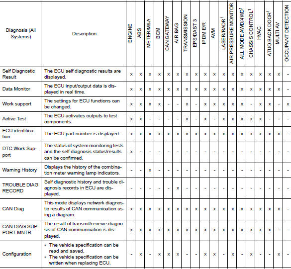
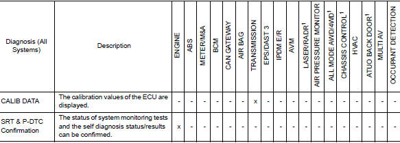
x: Applicable
1: If equipped
CONSULT Data Link Connector (DLC) Circuit
INSPECTION PROCEDURE
If the CONSULT cannot diagnose the system properly, check the following items.
| Symptom | Check item |
| CONSULT cannot access any system. |
|
| CONSULT cannot access individual system. (Other systems can be accessed.) |
|
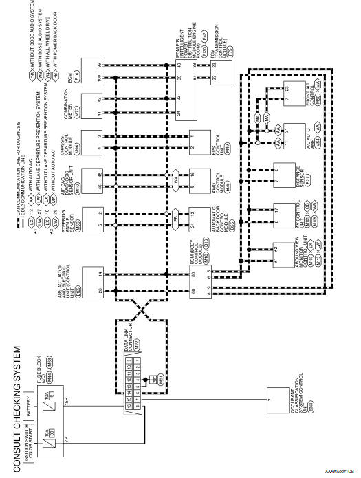
NOTE: The DDL2 circuits and CAN communication lines from DLC pins 6, 7 and 14 may be connected to more than one system. A short in a DDL circuit or CAN lines connected to a control unit in one system may affect CONSULT access to other systems. For a complete DDL circuit layout, refer to GI-51, "Wiring Diagram - CONSULT/ GST CHECKING SYSTEM". For a complete CAN line layout, refer to LAN-35, "Wiring Diagram - CAN SYSTEM -".
Wiring Diagram - CONSULT/GST CHECKING SYSTEM
 Circuit inspection
DESCRIPTION
In general, testing electrical circuits is an easy task if it is
approached in a logical and organized method.
Before beginning it is important to have all available informa ...
 Engine
...
Other materials:
How to use the touch-screen
CAUTION
The glass display screen may break if it
is hit with a hard or sharp object. If the
glass screen breaks, do not touch it.
Doing so could result in an injury.
To clean the display, never use a rough
cloth, alcohol, benzine, thinner or any
kind of ...
Periodic maintenance
FRONT SUSPENSION ASSEMBLY
Inspection
COMPONENT
Check the conditions (looseness, backlash) of each component. Verify the
component conditions (wear, damage)
are normal.
Ball Joint Axial End Play
Set front wheels in a straight-ahead position.
Move axle side of transverse link, ...
Preparation
Special Service Tools
The actual shape of the tools may differ from those illustrated here.
Tool number
(TechMate No.)
Tool name
Description
—
(165-GR8-1200KIT-NI)
Multitasking battery and electrical diagnostic
station
Testing batteries, start ...
