Nissan Rogue Service Manual: Glove box assembly and housing
Removal and Installation
REMOVAL
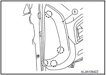
- Release instrument side finisher (RH) (1) pawls using a suitable tool and remove.
 : Pawl
NOTE: LH side shown; RH similar.
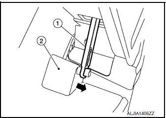
- Release the glove box damper (1) from the glove box assembly (2) as shown.
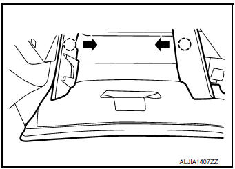
- Release the glove box assembly pawls as shown.
: Pawl
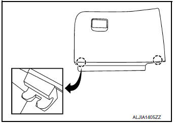
- Release the pawls and remove the glove box assembly.: Pawl
- Remove instrument finisher E. Refer to IP-16, "INSTRUMENT FINISHER E : Removal and Installation".
- Remove audio unit (DISPLAY AUDIO). Refer to AV-64, "Removal and Installation"
- Remove AV control unit. Refer to AV-209, "Removal and Installation" (NAVIGATION WITHOUT BOSE) or AV-376, "Removal and Installation" (NAVIGATION WITH BOSE).
- Remove front air control or A/C switch assembly. Refer to HAC-181, "Removal and Installation" (MANUAL AIR CONDITIONING) or HAC-102, "Removal and Installation" (AUTOMATIC AIR CONDITIONING).
- . Remove the glove box housing screws (A).
- Release the clips using a suitable tool, disconnect the harness
connector and remove glove box housing.
 : Metal clip
INSTALLATION
Installation is in the reverse order of removal.
 Instrument lower panel LH
Removal and Installation
REMOVAL
Release instrument side finisher (LH) (1) pawls using a suitable
tool and remove.
: Pawl
Remove bolts (A) and fuel filler lid/hood lock release ...
 Unit disassembly and assembly
CENTER CONSOLE ASSEMBLY
Exploded View
Center console cup holder (without
heated seats)
Coin tray insert
Center console cup holder (with
heated seats)
Front heated ...
Other materials:
P0507 ISC system
Description
The ECM controls the engine idle speed to a specified level through the fine
adjustment of the air, which is let
into the intake manifold, by operating the electric throttle control actuator.
The operating of the throttle valve is
varied to allow for optimum control of the engine ...
Power window relay
Description
Power is supplied to the main power window and door lock/unlock with BCM
control.
Component Function Check
1. CHECK POWER WINDOW RELAY POWER SUPPLY CIRCUIT
Check that an operation noise of power window relay [located behind the A/C
switch assembly (automatic A/
C) or Front air c ...
Tilt/telescopic steering
WARNING
Do not adjust the steering wheel while
driving. You could lose control of your
vehicle and cause an accident.
Do not adjust the steering wheel any
closer to you than is necessary for
proper steering operation and comfort.
The driver’s air bag ...
