
Nissan Rogue Service Manual: Component parts
Component Parts Location
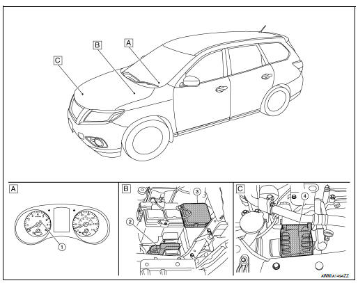
- Combination meter
- Engine room right side
- Engine room left side
|
No. |
Component part |
Description |
| 1 | Combination meter (Charge warning lamp) | The IC regulator warning function activates to illuminate the charge
warning
lamp if any of the following symptoms occur while generator is
operating:
|
| 2 | ECM | ECM transmits a target power generation voltage signal received from IPDM E/R to the generator via LIN communication. In addition, the ECM controls the charge warning lamp via CAN communication to the combination meter. |
| 3 | IPDM E/R | The IPDM E/R receives the generator signals via CAN communication from ECM. |
| 4 | Generator (IC voltage regulator) | IC voltage regulator controls the power generation voltage by the
target
power generation voltage based on the received signal.
When there is no power generation command signal, the generator performs the normal power generation according to the characteristic of the IC voltage regulator. |

 System
CHARGING SYSTEM
CHARGING SYSTEM : System Description
The generator provides DC voltage to operate the vehicle's electrical system
and to keep the battery charged.
The voltage output is cont ...
Other materials:
System
System Description
SYSTEM DIAGRAM
POWER WINDOW OPERATION
Main power window and door lock/unlock switch can open/close all
windows.
Front and rear power window switches can open/close the
corresponding windows.
POWER WINDOW AUTO-OPERATION (FRONT DRIVER SIDE)
AUTO UP/DOW ...
Brake pedal vibration or operation sound occurs
Description
Brake pedal vibrates and motor sound from ABS actuator and electric unit
(control unit) occurs, when the
engine starts.
Brake pedal vibrates during braking.
CAUTION:
Vibration may be felt during brake pedal is lightly depressed (just placing a
foot on it) in the fo ...
System
METER SYSTEM
METER SYSTEM : System Description
SYSTEM DIAGRAM
Combination Meter Input Signal (CAN Communication Signal)
DESCRIPTION
Combination Meter
The combination meter controls the following items according to
the signals received from each unit via CAN
communicat ...
