Nissan Rogue Service Manual: Unit removal and installationEMBER
REAR SUSPENSION M
Exploded View
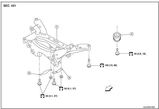
- Rear suspension member
- Suspension member stay (RH)
- Suspension member stay (LH)
- Bound bumper
 Front
Front
Removal and Installation - FWD
REMOVAL
- Remove wheel and tires using power tool. Refer to WT-60, "Exploded View".
- Remove muffler assembly. Refer to EX-5, "Exploded View".
- Remove coil spring. Refer to RSU-8, "Removal and Installation - FWD".
- Remove lower link. Refer to RSU-17, "Removal and Installation".
- Remove upper link. Refer to BR-43, "BRAKE CALIPER ASSEMBLY : Removal and Installation".
- Remove rear stabilizer bar.Refer to RSU-21, "Removal and Installation".
- Remove rear shock absorber. Refer to RSU-14, "Removal and Installation".
- Set suitable jack under rear suspension member.
- Remove bolts from rear suspension member.
- Slowly lower suitable jack and remove rear suspension member.
CAUTION: Secure suspension assembly to a suitable jack while removing it.
INSTALLATION Installation is in the reverse order of the removal.
- When installing suspension member stay, face each arrow on the part toward the inside of the vehicle.
- Align the matching marks made during removal when reusing the disc brake rotor.
- Perform the final tightening of each parts removed when removing rear suspension assembly under unladen conditions.
- Check wheel sensor harness for proper connection. Refer to BRC-133, "REAR WHEEL SENSOR : Exploded View".
Removal and Installation - AWD
REMOVAL
- Remove wheel and tires using power tool. Refer to WT-60, "Exploded View".
- Remove muffler assembly. Refer to EX-5, "Exploded View".
- Remove coil spring. Refer to RSU-10, "Removal and Installation - AWD".
- Remove lower link. Refer to RSU-17, "Removal and Installation".
- Remove upper link. Refer to BR-43, "BRAKE CALIPER ASSEMBLY : Removal and Installation".
- Remove rear stabilizer bar.Refer to RSU-21, "Removal and Installation".
- Remove rear drive shaft. Refer to RAX-19, "Removal and Installation".
- Remove rear propeller shaft. Refer to DLN-99, "Removal and Installation".
- Remove rear final drive. Refer to DLN-119, "Removal and Installation".
- Remove rear shock absorber. Refer to RSU-14, "Removal and Installation".
- Set suitable jack under rear suspension member.
- Remove bolts from rear suspension member.
- Slowly lower suitable jack and remove rear suspension member.
CAUTION: Secure suspension assembly to a suitable jack while removing it.
- Perform the inspection after removal. Refer to RSU-23, "Inspection".
INSTALLATION
Installation is in the reverse order of the removal.
- When installing suspension member stay, face each arrow on the part toward the inside of the vehicle.
- Align the matching marks made during removal when reusing the disc brake rotor.
- Perform the final tightening of each parts removed when removing rear suspension assembly under unladen conditions.
- Check wheel sensor harness for proper connection. Refer to BRC-133, "REAR WHEEL SENSOR : Exploded View".
- Perform the inspection after installation. Refer to RSU-20,
"Inspection".
Inspection
INSPECTION AFTER REMOVAL
Check rear suspension member for deformation, cracks, or any other damage. Replace it if necessary.
INSPECTION AFTER INSTALLATION
- Adjust parking brake operation. Refer to PB-4, "Inspection and Adjustment".
- Check wheel alignment. Refer to RSU-6, "Inspection".
 Rear stabilizer
Exploded View
Rear stabilizer bar
Connecting rod (RH)
Rear stabilizer bar bushing
Rear stabilizer bar clamp
Connecting rod (LH)
Front
Removal and ...
 Service data and specifications (SDS)
Wheel Alignment (Unladen*1)
*1: Fuel, engine coolant, and lubricants are full. Spare tire, jack, hand
tools, and mats are in designated positions.
*2: Since an adjustment mechanism is not incl ...
Other materials:
Regulatory Information
FCC Regulatory information
CAUTION: To maintain compliance with
FCC’s RF exposure guidelines, use only the
supplied antenna. Unauthorized antenna,
modification, or attachments could damage
the transmitter and may violate FCC regulations.
Operation is subject to the follow ...
Headlight control switch
Type A (if so equipped)
When turning the switch to the
position,
the front parking, tail, license plate and
instrument panel lights come on.
When turning the switch to the
position,
the headlights come on and all the other
lights remain on.
Type B (if so equipped)
...
Fuel gauge
Fuel gauge
The gauge indicates the approximate fuel level
in the tank.
The gauge may move slightly during braking,
turning, acceleration, or going up or down hills.
The gauge needle returns to 0 (Empty) after the
ignition switch is placed in the OFF position.
The low fuel warning ligh ...
