Nissan Rogue Service Manual: Unit disassembly and assembly
CENTER CONSOLE ASSEMBLY
Exploded View
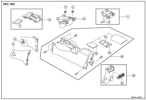
- Center console cup holder (without heated seats)
- Coin tray insert
- Center console cup holder (with heated seats)
- Front heated seat switch (RH)
- Front heated seat switch (LH)
- Shift selector finisher
- Shift selector finisher mat
- Center console side finisher (RH)
- Center console side finisher (LH)
- Center console bin mat
- Center console tray
- Center console rear brace finisher
- Center console assembly
- Rear center ventilator grille
- Center console rear finisher
 Metal clip
 Clip
Clip
 Pawl
Pawl
Disassembly and Assembly
DISASSEMBLY
- Remove center console assembly. Refer to IP-18, "Removal and Installation".
- Remove the center console bin mat. Refer to IP-25, "Exploded View".
- Release clips using a suitable tool and remove shift selector
finisher.: Metal clip
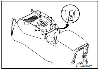
- Release clips and pawls using a suitable tool and remove center console cup holder.
: Metal clip
: Pawl
- Release pawls and remove center console rear brace finisher. Refer to IP-25, "Exploded View".
- Remove screws and center console tray. Refer to IP-25, "Exploded View".
ASSEMBLY
Assembly is in the reverse order of disassembly.
 Glove box assembly and housing
Removal and Installation
REMOVAL
Release instrument side finisher (RH) (1) pawls using a suitable
tool and remove.
: Pawl
NOTE:
LH side shown; RH similar.
Release the glove box ...
 Seat
Seat
...
Other materials:
Speedometer and odometer
Speedometer
The speedometer indicates vehicle speed.
Odometer/Twin trip odometer
The odometer 1 and the twin trip odometer 2
are displayed below the Vehicle Information Display
when the ignition switch is placed in the ON
position.
The odometer records the total distance the vehicle
has ...
RearView Monitor (if so equipped)
When the shift lever is shifted into the R (Reverse)
position, the monitor display shows the
view to the rear of the vehicle.
WARNINGFailure to follow the warnings and instructions
for proper use of the RearView
Monitor could result in serious injury or
death.
The Re ...
EPS warning lamp
Component Function Check
1.CHECK THE ILLUMINATION OF THE EPS WARNING LAMP
Check that the EPS warning lamp turns ON when ignition switch turns ON. Then,
EPS warning lamp turns
OFF after the engine is started.
Is the inspection result normal?
YES >> Inspection End.
NO >> Perfor ...
