Nissan Rogue Service Manual: U1050, U1051 LIN communication
DTC Description
DTC DETECTION LOGIC
| DTC No. | CONSULT screen terms (Trouble diagnosis content) | DTC detecting condition |
| U1050 | LIN COMMUNICATION [LIN (Local Interconnect Network) communication)] | ECM detects LIN communication error. |
| U1051 |
POSSIBLE CAUSE
- Harness or connectors (LIN communication circuit is open or shorted.)
- Generator
- ECM
FAIL-SAFE
Not applicable
DTC CONFIRMATION PROCEDURE
1.PRECONDITIONING
If DTC Confirmation Procedure has been previously conducted. always perform the following procedure before conducting the next test.
- Turn ignition switch OFF and wait at least 10 seconds.
- Turn ignition switch ON.
- Turn ignition switch OFF and wait at least 10 seconds.
>> GO TO 2.
2.PERFORM DTC CONFIRMATION PROCEDURE
- Turn ignition ON and wait at least 10 seconds.
- Check DTC.
Is DTC detected? YES >> Proceed to EC-175, "Diagnosis Procedure".
NO >> INSPECTION END
Diagnosis Procedure
1.CHECK LIN COMMUNICATION CIRCUIT
- Turn ignition switch OFF.
- Disconnect ECM harness connector and generator harness connector.
- Check the continuity between ECM harness connector and generator harness connector.
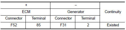
- Also check harness for short to power and short to ground.
Is the inspection result normal? YES >> GO TO 2.
NO >> Repair or replace error-detected parts.
2.REPLACE GENERATOR
- Replace generator. Refer to CHG-20, "Removal and Installation".
- Erase DTC.
- Perform DTC confirmation procedure again. Refer to EC-175, "DTC Description".
Is DTC detected again? YES >> Replace ECM. Refer to EC-499, "Removal and Installation".
NO >> INSPECTION END
 U1044 ENG comm circuit
DTC Description
DTC DETECTION LOGIC
DTC No.
CONSULT screen terms
(Trouble diagnosis content)
DTC detecting condition
U1044
ENG COMM CIRCUIT
(Engine communication circu ...
 P0011 IVT control
DTC Description
DTC DETECTION LOGIC
DTC No.
CONSULT screen terms
(Trouble diagnosis content)
DTC detecting condition
P0011
INT/V TIM CONT-B1
(″A″ Camshaft ...
Other materials:
How to select piston and bearing
DESCRIPTION
Selection points
Selection parts
Selection items
Selection methods
Between cylinder block to
crankshaft
Main bearing
Main bearing grade (bearing
thickness)
Determined by match of cylinder
block bearing housing
grade (inner diameter of housin ...
Cluster lid A
Removal and Installation
REMOVAL
Remove instrument lower panel LH. Refer to IP-22, "Removal and
Installation".
Remove instrument finisher A. Refer to IP-15, "INSTRUMENT FINISHER
A : Removal and Installation".
Remove instrument finisher B. Refer to ...
Intermittent incident
DESCRIPTION
Sometimes the symptom is not present when the vehicle is brought in for
service. If possible, re-create the
conditions present at the time of the incident. Doing so may help avoid a No
Trouble Found Diagnosis. The following section illustrates ways to simulate the
conditions/envi ...
