
Nissan Rogue Service Manual: Component parts
Component Parts Location
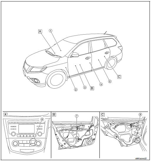
- A/C switch assembly
- View with front door finisher removed
- View with rear door finisher removed
|
No. |
Component parts |
Function |
| 1 | Front power window switch | Refer to PWC-7, "Power Window Switch". |
| 2 | BCM |
|
| 3 | Main power window and door lock/unlock switch | Refer to PWC-7, "Power Window Main Switch". |
| 4 | Front door switch LH (RH similar) |
|
| 5 | Rear power window switch LH (RH similar) | Refer to PWC-7, "Power Window Switch". |
| 6 | Power window relay | Operates the power window system with the control signal from the BCM. |
| 7 | Front power window motor LH (RH similar) | Refer to PWC-7, "Power Window Motor". |
| 8 | Rear power window motor LH (RH similar) | Refer to PWC-7, "Power Window Motor". |
Power Window Main Switch
- Main power window and door lock/unlock switch controls all power windows.
- Main power window and door lock/unlock switch integrates UP/ DOWN switch, power window lock switch, and door lock/unlock switch.
- Main power window and door lock/unlock switch controls power window lock function, AUTO UP/DOWN function, and anti-pinch function.
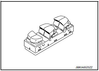
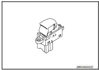
Power Window Switch
- Each power window switch transmits UP/DOWN signal to each motor.
- Each power window switch transmits UP/DOWN signal from power window main switch to each motor.
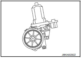
Power Window Motor
- Integrates the encoder and power window motor (front driver side).
- Starts operation according to signals from main power window and door lock/unlock switch.
- Transmits front power window motor (driver side) rotation as a pulse signal to power window main switch.
- Excepting power window motor for driver door, starts operation according to signals from main power window and door lock/unlock switch or each power window switches.

 System
 Description
SYSTEM DIAGRAM
POWER WINDOW OPERATION
Main power window and door lock/unlock switch can open/close all
windows.
Front and rear power window switches can open/cl ...
Other materials:
Door mirror glass
Removal and Installation
REMOVAL
Release the metal clips and pawls that retain the door mirror
glass using a suitable tool, disconnect the harness connectors
(A) (if equipped) from the door mirror glass and remove.
Metal clip
: Pawl
INSTALLATION
Installation is in the rever ...
Rear wiper motor
Exploded View
Rear wiper motor
Back door
Rear wiper motor harness
Removal and Installation
REMOVAL
Remove rear wiper arm. Refer to WW-69, "Removal and Installation".
Remove back door finisher. Refer to INT-38, "Removal and
Installation".
& ...
None of the power windows can be operated using any
switch
Diagnosis Procedure
1.CHECK BCM POWER SUPPLY AND GROUND CIRCUIT
Check BCM power supply and ground circuit.
Refer to BCS-68, "Diagnosis Procedure" (with Intelligent Key system) or BCS-128,
"Diagnosis Procedure"
(without Intelligent Key system).
Is the inspection result ...
