Nissan Rogue Service Manual: Precaution
Precaution for Supplemental Restraint System (SRS) "AIR BAG" and "SEAT BELT PRE-TENSIONER"
The Supplemental Restraint System such as “AIR BAG” and “SEAT BELT PRE-TENSIONER”, used along with a front seat belt, helps to reduce the risk or severity of injury to the driver and front passenger for certain types of collision. Information necessary to service the system safely is included in the SR and SB section of this Service Manual.
WARNING:
- To avoid rendering the SRS inoperative, which could increase the risk of personal injury or death in the event of a collision which would result in air bag inflation, all maintenance must be performed by an authorized NISSAN/INFINITI dealer.
- Improper maintenance, including incorrect removal and installation of the SRS, can lead to personal injury caused by unintentional activation of the system. For removal of Spiral Cable and Air Bag Module, see the SR section.
- Do not use electrical test equipment on any circuit related to the SRS unless instructed to in this Service Manual. SRS wiring harnesses can be identified by yellow and/or orange harnesses or harness connectors.
PRECAUTIONS WHEN USING POWER TOOLS (AIR OR ELECTRIC) AND HAMMERS
WARNING:
- When working near the Airbag Diagnosis Sensor Unit or other Airbag System sensors with the Ignition ON or engine running, DO NOT use air or electric power tools or strike near the sensor(s) with a hammer. Heavy vibration could activate the sensor(s) and deploy the air bag(s), possibly causing serious injury.
- When using air or electric power tools or hammers, always switch the Ignition OFF, disconnect the battery and wait at least three minutes before performing any service.
Liquid Gasket
REMOVAL OF LIQUID GASKET SEALING
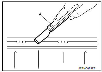
- After removing the bolts and nuts, separate the mating surface and remove the liquid gasket using Tool (A).

Tool Number : KV10111100 (J-37228)
CAUTION:
Be careful not to damage the mating surfaces.
- In areas where the cutter is difficult to use, use a plastic hammer to lightly tap (1) the cutter where the liquid gasket is applied. Use a plastic hammer to slide (2) the cutter by tapping on the side.
CAUTION: Do not damage the mating surfaces.
LIQUID GASKET APPLICATION PROCEDURE
- Using suitable tool (A), remove old liquid gasket adhering to the liquid gasket application surface and the mating surface.
- Remove liquid gasket completely from the groove of the liquid gasket application surface, mounting bolts, and bolt holes.
- Thoroughly clean the mating surfaces and remove adhering moisture, grease and foreign material.
- Attach liquid gasket tube to the suitable tool.
Use Genuine Silicone RTV Sealant, or equivalent. Refer to GI-22, "Recommended Chemical Products and Sealants".
- Apply liquid gasket without gaps to the specified location according to the specified dimensions.
- If there is a groove for liquid gasket application, apply liquid gasket to the groove.
- As for bolt holes (B), normally apply liquid gasket inside the
holes. Occasionally, it should be applied outside the holes.
Check to read the text of this manual.
(A) : Groove
 : Inside
- Within five minutes of liquid gasket application, install the mating component.
- If liquid gasket protrudes, wipe it off immediately.
- Do not retighten mounting bolts or nuts after the installation.
- After 30 minutes or more have passed from the installation, fill engine oil. Refer to LU-8, "Refilling".
CAUTION: If there are specific instructions in the procedures contained in this manual concerning liquid gasket application, observe them.

 Preparation
Special Service Tools
The actual shape of the tools may differ from those illustrated here.
Tool number
(TechMate No.)
Tool name
Description
KV10111100
(J-37228)
...
Other materials:
System
System Description
SYSTEM DIAGRAM
OPERATION DESCRIPTION
When rear window defogger switch is turned ON while ignition
switch is ON, the rear window defogger
switch transmits rear window defogger switch signal to BCM.
BCM turns rear window defogger relay ON when rear windo ...
Service data and specifications (SDS)
General Specifications
Preload Torque
Drive Gear Runout
Backlash
Differential Side Gear Clearance
...
Retained power operation does not operate properly
Diagnosis Procedure
1.CHECK FRONT DOOR SWITCH
Check (LH and RH) front door switches.
Refer to DLK-24, "Front Door Switch".
Is the inspection result normal?
YES >> GO TO 2.
NO >> Repair or replace the malfunctioning parts.
2.CONFIRM THE OPERATION
Confirm the operat ...
