Nissan Rogue Service Manual: Power supply and ground circuit
BCM (BODY CONTROL SYSTEM) (WITH INTELLIGENT KEY SYSTEM)
BCM (BODY CONTROL SYSTEM) (WITH INTELLIGENT KEY SYSTEM) : Diagnosis Procedure
Regarding Wiring Diagram information, refer to BCS-50, "Wiring Diagram".
1. CHECK FUSE
Check that the following fuse is not blown.

Is the fuse blown? YES >> Replace the blown fuse after repairing the affected circuit.
NO >> GO TO 2.
2. CHECK POWER SUPPLY CIRCUIT
- Disconnect BCM connector M20.
- Check voltage between BCM connector M20 and ground.
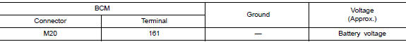
Is the inspection result normal? YES >> GO TO 3.
NO >> Repair or replace harness or connectors.
3. CHECK GROUND CIRCUIT
Check continuity between BCM connector M20 and ground.
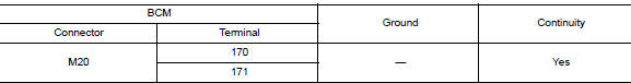
Is the inspection result normal? YES >> Inspection End.
NO >> Repair or replace harness or connectors.
BCM (BODY CONTROL SYSTEM) (WITHOUT INTELLIGENT KEY SYSTEM)
BCM (BODY CONTROL SYSTEM) (WITHOUT INTELLIGENT KEY SYSTEM) : Diagnosis Procedure
Regarding Wiring Diagram information, refer to BCS-110, "Wiring Diagram".
1. CHECK FUSE
Check that the following fuse is not blown.

Is the fuse blown? YES >> Replace the blown fuse after repairing the affected circuit.
NO >> GO TO 2.
2. CHECK POWER SUPPLY CIRCUIT
- Disconnect BCM connector M20.
- Check voltage between BCM connector M20 and ground.
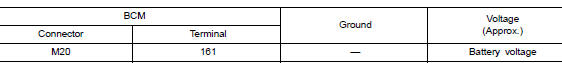
Is the inspection result normal? YES >> GO TO 3.
NO >> Repair or replace harness or connectors.
3. CHECK GROUND CIRCUIT
Check continuity between BCM connector M20 and ground.
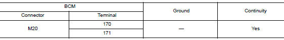
Is the inspection result normal? YES >> Inspection End.
NO >> Repair or replace harness or connectors.
POWER WINDOW MAIN SWITCH
POWER WINDOW MAIN SWITCH : Diagnosis Procedure
1.CHECK POWER SUPPLY CIRCUIT 1
- Turn ignition OFF.
- Disconnect main power window and door lock/unlock switch connector.
- Turn ignition switch ON.
- Check voltage between main power window and door lock/unlock switch harness connector and ground.
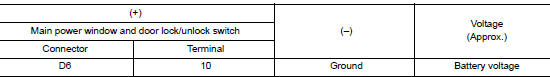
Is the inspection result normal? YES >> GO TO 2.
NO >> GO TO 4.
2.CHECK POWER SUPPLY CIRCUIT 2
1. Check voltage between main power window and door lock/unlock switch harness connector and ground.
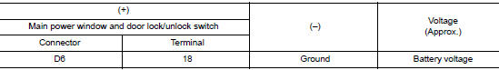
Is the inspection result normal? YES >> GO TO 3.
NO >> Repair power supply circuit.
3.CHECK GROUND CIRCUIT
- Turn ignition switch OFF.
- Check continuity between main power window and door lock/unlock switch harness connector and ground.
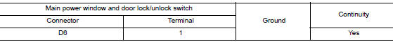
Is the inspection result normal? YES >> Inspection End.
NO >> Repair or replace harness.
4.CHECK HARNESS CONTINUITY 1
- Turn ignition switch OFF.
- Disconnect power window relay connector.
- Check continuity between power window relay harness connector and main power window and door lock/ unlock switch harness connector.
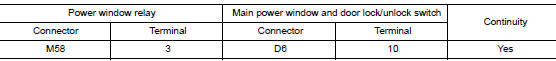
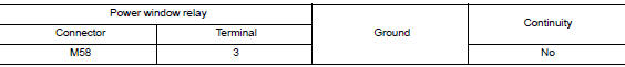
- Check continuity between power window relay harness connector and ground.
Is the inspection result normal? YES >> Refer to PWC-48, "Diagnosis Procedure".
NO >> Repair or replace harness.
FRONT POWER WINDOW SWITCH (PASSENGER SIDE)
FRONT POWER WINDOW SWITCH (PASSENGER SIDE) : Diagnosis Procedure
1.CHECK POWER SUPPLY CIRCUIT
- Turn ignition switch OFF.
- Disconnect front power window switch RH connector.
- Turn ignition switch ON.
- Check voltage between front power window switch RH harness connector and ground.
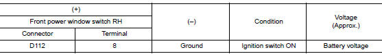
Is the inspection result normal? YES >> Inspection End.
NO >> GO TO 2.
2.CHECK HARNESS CONTINUITY
- Turn ignition switch OFF.
- Disconnect power window relay connector.
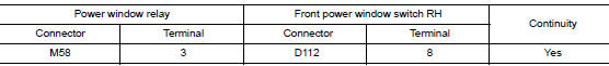
- Check continuity between power window relay harness connector and front power window switch RH harness connector.
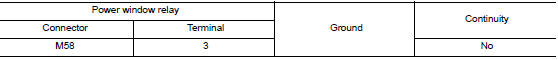
- Check continuity between the power window relay harness connector and ground.
Is the inspection result normal? YES >> Refer to PWC-48, "Diagnosis Procedure".
NO >> Repair or replace harness.
REAR POWER WINDOW SWITCH
REAR POWER WINDOW SWITCH : Diagnosis Procedure
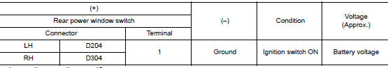
1.CHECK POWER SUPPLY CIRCUIT
- Turn ignition switch OFF.
- Disconnect rear power window switch connector.
- Turn ignition switch ON.
- Check voltage between rear power window switch harness connector and ground.
Is the inspection result normal? YES >> Inspection End.
NO >> GO TO 2.
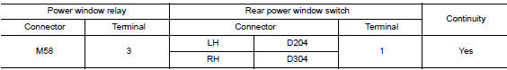
2.CHECK HARNESS CONTINUITY
- Turn ignition switch OFF.
- Disconnect power window relay connector.
- Check continuity between power window relay harness connector and rear power window switch harness connector.
- Check continuity between power window relay harness connector and ground.
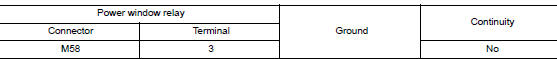
Is the inspection result normal? YES >> Refer to PWC-48, "Diagnosis Procedure".
NO >> Repair or replace harness.

 Front power window switch (passenger side)
Description
Front power window motor RH will be operated if front power window switch RH
is operated.
Component Function Check
1. CHECK FRONT POWER WINDOW SWITCH RH FUNCTION
Check front power wi ...
Other materials:
Preparation
Special Service Tool
The actual shape of the tools may differ from those illustrated here.
Tool number
(TechMate No.)
Tool name
Description
—
(J-46534)
Trim Tool Set
Removing trim components
Commercial Service Tools
(TechMate No ...
Diagnosis and repair work flow
Work Flow
OVERALL SEQUENCE
DETAILED FLOW
1.INTERVIEW THE CUSTOMER FOR THE SYMPTOM
Interview the customer for the symptom (the condition and the environment
when the incident/malfunction
occurs).
>> GO TO 2.
2.CHECK SYMPTOM
Check the symptom from the customer information.
> ...
Sunshade
Removal and Installation
REMOVAL
Remove the moonroof unit assembly. Refer to RF-53, "Removal and
Installation".
Place the moonroof unit assembly (1) on a flat surface upside
down and remove sunshade (2) screws (A).
Manually move sunshade motor (1) using suitable tool (2 ...
