
Nissan Rogue Owners Manual: Passenger compartment
| CAUTION Never use a fuse of a higher or lower amperage rating than specified on the fuse box cover. This could damage the electrical system or cause a fire. |
If any electrical equipment does not operate, check for an open fuse.
NOTE: The fuse box is located on the driver’s side of the instrument panel.
- Be sure the ignition switch and the headlight switch are OFF.
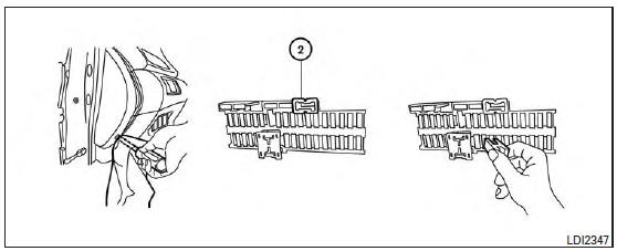
- Remove the fuse box cover with a suitable tool. Use a cloth to avoid damaging the trim.
- Locate the fuse that needs to be replaced.
- Remove the fuse with the fuse puller 2 .
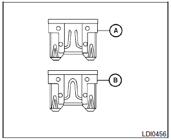
- If the fuse is open A , replace it with an equivalent good fuse B .
- Push the fuse box cover to install.
If a new fuse also opens, have the electrical system checked and repaired by a NISSAN dealer.
Extended storage switch
If any electrical equipment does not operate, remove the extended storage switch and check for an open fuse.
NOTE: The extended storage switch is used for long term vehicle storage. Even if the extended storage switch is broken it is not necessary to replace it. Replace only the open fuse in the switch with a new fuse. How to replace the extended storage switch:
- To remove the extended storage switch, be sure the ignition switch is in the OFF or LOCK position.
- Be sure the headlight switch is in the OFF position.
- Remove the fuse box cover.
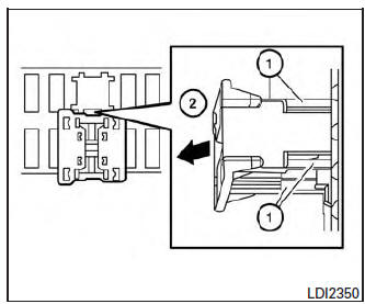
- Pinch the locking tabs 1 found on each side of the storage switch.
- Pull the storage switch straight out from the fuse box 2 .
 Engine compartment
CAUTIONNever use a fuse of a higher or lower
amperage rating than specified on the
fuse box cover. This could damage the
electrical system or cause a fire.
Two types of fuses ...
 Battery replacement
CAUTIONBe careful not to allow children to swallow
the battery or removed parts.
...
Other materials:
Controls
Fan control dial
The fan control dial turns the fan on and off, and
controls fan speed.
Air flow control buttons
The air flow control buttons allow you to select
the air flow outlets.
MAX A/C — Air flows mainly from center and
side vents with maximum cooling
and turns on.
— Air flows m ...
Precaution
Precaution for Supplemental Restraint System (SRS) "AIR BAG" and "SEAT
BELT
PRE-TENSIONER"
The Supplemental Restraint System such as “AIR BAG� and “SEAT BELT PRE-TENSIONER�,
used along
with a front seat belt, helps to reduce the risk or severity of injury to the
...
Unit removal and installation
TRANSAXLE ASSEMBLY
Exploded View
Transaxle assembly
O-ring
CVT fluid charging pipe
CVT fluid charging pipe cap
For the tightening torque, refer to TM-220, "Removal and
Installation".
Always replace after every
disassembly.
: N·m (kg-m, ft-lb)
: N·m ...
