Nissan Rogue Service Manual: P2014, P2016, P2017, P2018 intake manifold runner control valve position sensor
DTC Description
DTC DETECTION LOGIC
| DTC No. | CONSULT screen terms (Trouble diagnosis content) | DTC detecting condition |
| P2014 | IN/MANIFOLD RUNNER POS SEN B1 (Intake manifold runner position sensor/ switch circuit bank 1) | An excessively low voltage from the sensor is sent to ECM. |
| P2016 | IN/MANIFOLD RUNNER POS SEN B1 (Intake manifold runner position sensor/ switch circuit low bank 1) | |
| P2017 | IN/MANIFOLD RUNNER POS SEN B1 (Intake manifold runner position sensor/ switch circuit high bank 1) | An excessively high voltage from the sensor is sent to ECM. |
| P2018 | IN/MANIFOLD RUNNER POS SEN B1 (Intake manifold runner position sensor/ switch circuit intermittent bank 1) |
POSSIBLE CAUSE
- Harness or connectors (Intake manifold runner control position sensor circuit is shorted.)
- Intake manifold runner control position sensor
FAIL-SAFE
Not applicable
DTC CONFIRMATION PROCEDURE
1.CHECK DTC PRIORITY
If DTC P2014, P2016, P2017 or P2018 is displayed with DTC P0643, first perform the trouble diagnosis for DTC P0643.
Is applicable DTC detected? YES >> Perform diagnosis of applicable. Refer to EC-379, "DTC Description".
NO >> GO TO 2.
2.PRECONDITIONING
If DTC Confirmation Procedure has been previously conducted, always perform the following before conducting the next test.
- Turn ignition switch OFF and wait at least 10 seconds.
- Turn ignition switch ON.
- Turn ignition switch OFF and wait at least 10 seconds.
TESTING CONDITION: Before performing the following procedure, confirm that battery voltage is more than 11 V at idle. >> GO TO 3.
3.PERFORM DTC CONFIRMATION PROCEDURE
- Start engine and let it idle for 10 seconds.
- Check 1st trip DTC.
Is 1st trip DTC detected? YES >> Proceed to EC-424, "Diagnosis Procedure".
NO >> INSPECTION END
Diagnosis Procedure
1.CHECK DTC PRIORITY
If DTC P2014, P2016, P2017 or P2018 is displayed with DTC P0643, first perform the trouble diagnosis for DTC P0643.
Is applicable DTC detected? YES >> Perform diagnosis of applicable. Refer to EC-379, "DTC Description".
NO >> GO TO 2.
2.CHECK INTAKE MANIFOLD RUNNER CONTROL VALVE POSITION SENSOR POWER SUPPLY
- Turn ignition switch OFF.
- Disconnect intake valve manifold runner control valve position sensor harness connector.
- Turn ignition switch ON.
- Check the voltage between intake valve manifold runner control valve position sensor harness connector.
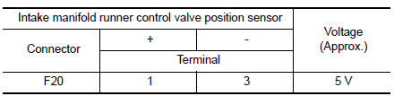
Is the inspection result normal? YES >> GO TO 5.
NO >> GO TO 3.
3.CHECK INTAKE MANIFOLD RUNNER CONTROL VALVE POSITION SENSOR POWER SUPPLY CIRCUIT
Check the voltage between intake valve manifold runner control valve position sensor harness connector and ground.
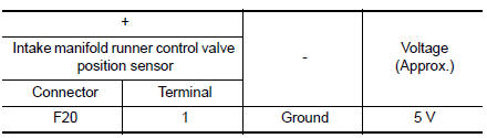
Is the inspection result normal? YES >> GO TO 4.
NO >> Perform the trouble diagnosis for power supply circuit.
4.CHECK ECM GROUND CIRCUIT
- Turn ignition switch OFF.
- Disconnect ECM harness connector.
- Check the continuity between ECM harness connector and ground.
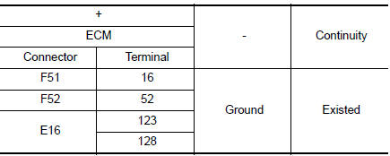
- Also check harness for short to power.
Is the inspection result normal? YES >> GO TO 8.
NO >> Repair or replace error-detected parts.
5.CHECK INTAKE MANIFOLD RUNNER CONTROL VALVE POSITION SENSOR GROUND CIRCUIT
- Turn ignition switch OFF.
- Disconnect ECM harness connector.
- Check the continuity between intake manifold runner control valve position sensor harness connector and ECM harness connector.
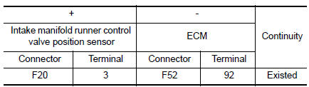
- Also check harness for short to power.
Is the inspection result normal? YES >> GO TO 6.
NO >> Repair or replace error-detected parts.
6.CHECK INTAKE MANIFOLD RUNNER CONTROL VALVE POSITION SENSOR INPUT SIGNAL CIRCUIT
- Check the continuity between intake manifold runner control valve position sensor harness connector and ECM harness connector.
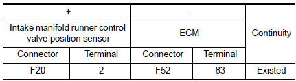
- Also check harness for short to ground and to power.
Is the inspection result normal? YES >> GO TO 7.
NO >> Repair or replace error-detected parts.
7.CHECK INTERMITTENT INCIDENT
Perform GI-41, "Intermittent Incident".
Is the inspection result normal? YES >> Replace intake manifold assembly. Refer to EM-26, "Exploded View".
NO >> Repair or replace error-detected parts.
8.CHECK INTERMITTENT INCIDENT
Refer to GI-41, "Intermittent Incident".
>> INSPECTION END
 P2004 intake manifold runner control valve
DTC Description
DTC DETECTION LOGIC
DTC No.
CONSULT screen terms
(Trouble diagnosis content)
DTC detecting condition
P2004
TUMBLE CONT/V
(Intake manifold runner contro ...
 P2096, P2097 A/F sensor 1
DTC Description
DTC DETECTION LOGIC
DTC No.
CONSULT screen terms
(Trouble diagnosis content)
DTC detecting condition
P2096
POST CATALYST FUEL TRIM SYS B1
(Post catalys ...
Other materials:
EVAP canister filter
Exploded View
EVAP canister vent control valve hose
Canister drain hose
Plug
EVAP canister filter
Front
Removal and Installation
REMOVAL
Disconnect EVAP canister vent control valve hose from EVAP
canister filter.
Disconnect canister drain hose from E ...
Ground
Ground Distribution
MAIN HARNESS
ENGINE ROOM HARNESS
ENGINE CONTROL HARNESS
BODY HARNESS
BODY NO. 2 HARNESS
...
DTC/circuit diagnosis
DOOR MIRROR REMOTE CONTROL SWITCH (MIRROR SWITCH/
CHANGEOVER SWITCH)
Component Inspection
1.CHECK MIRROR SWITCH & CHANGEOVER SWITCH
Turn ignition switch OFF.
Disconnect door mirror remote control switch connector.
Check door mirror remote control switch.
Is th ...
