Nissan Rogue Service Manual: P0966 pressure control solenoid B
DTC Description
DTC DETECTION LOGIC
| DTC | CONSULT screen terms (Trouble diagnosis content) | DTC detection condition |
| P0966 | PC SOLENOID B (Pressure Control Solenoid B Control Circuit Low) | When all of the following conditions are satisfied and this state is
maintained
for 0.48 seconds:
|
POSSIBLE CAUSE
- Harness or connector (Primary pressure solenoid valve circuit shorted to ground)
- Primary pressure solenoid valve
FAIL-SAFE
- Selector shock is large
- Start is slow
- Acceleration is slow
- Lock-up is not performed
DTC CONFIRMATION PROCEDURE
1.PREPARATION BEFORE WORK
If another "DTC CONFIRMATION PROCEDURE" occurs just before, turn ignition switch OFF and wait for at least 10 seconds, then perform the next test.
>> GO TO 2.
2.CHECK DTC DETECTION
- Start the engine and wait for 5 seconds or more.
- Check the first trip DTC.
Is “P0966” detected? YES >> Go to TM-163, "Diagnosis Procedure".
NO-1 >> To check malfunction symptom before repair: Refer to GI-41, "Intermittent Incident".
NO-2 >> Confirmation after repair: INSPECTION END
Diagnosis Procedure
1.CHECK CIRCUIT BETWEEN TCM AND CVT UNIT
- Turn ignition switch OFF.
- Disconnect TCM connector and CVT unit connector.
- Check continuity between TCM harness connector terminal and ground.
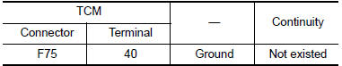
Is the inspection result normal? YES >> GO TO 2.
NO >> Repair or replace damaged parts.
2.CHECK CIRCUIT BETWEEN CVT UNIT AND GROUND
Check continuity between CVT unit harness connector terminal and ground.
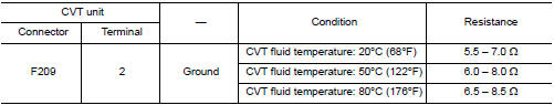
Is the inspection result normal? YES >> INSPECTION END
NO >> There is malfunction of primary pressure solenoid valve. Replace transaxle assembly. Refer to TM-220, "Removal and Installation".
 P0965 pressure control solenoid B
DTC Description
DTC DETECTION LOGIC
DTC
CONSULT screen terms
(Trouble diagnosis content)
DTC detection condition
P0965
PC SOLENOID B
(Pressure Control Solenoid B Contr ...
 P0967 pressure control solenoid B
DTC Description
DTC DETECTION LOGIC
DTC
CONSULT screen terms
(Trouble diagnosis content)
DTC detection condition
P0967
PC SOLENOID B
(Pressure Control Solenoid B Contr ...
Other materials:
Precaution
Precaution for Supplemental Restraint System (SRS) "AIR BAG" and "SEAT
BELT
PRE-TENSIONER"
The Supplemental Restraint System such as “AIR BAG” and “SEAT BELT PRE-TENSIONER”,
used along
with a front seat belt, helps to reduce the risk or severity of injury to the
...
Battery
How to Handle Battery
CAUTION:
If it becomes necessary to start the engine with a booster
battery and jumper cables, use a 12-volt
booster battery.
After connecting battery cables, ensure that they are tightly
clamped to battery terminals for good
contact.
Never ...
CVT oil warmer
Exploded View
Transaxle assembly
CVT oil warmer
: N·m (kg-m, in-lb)
Removal and Installation
REMOVAL
WARNING:
Do not remove the radiator cap when the engine is hot. Serious burns could occur
from high pressure
engine coolant escaping from the radiator. Wrap a thick cloth around ...
