Nissan Rogue Service Manual: P0197, P0198 EOT sensor
DTC Description
DTC DETECTION LOGIC
| DTC No. | CONSULT screen terms (Trouble diagnosis content) | DTC detecting condition |
| P0197 | EOT SEN/CIRC (Engine oil temperature sensor low) | An excessively low voltage from the engine oil temperature sensor is sent to ECM. |
| P0198 | EOT SEN/CIRC (Engine oil temperature sensor high) | An excessively high voltage from the engine oil temperature sensor is sent to ECM. |
POSSIBLE CAUSE
- Harness or connectors (EOT sensor circuit is open or shorted.)
- Engine oil temperature sensor
FAIL-SAFE
Exhaust valve timing control does not function.
DTC CONFIRMATION PROCEDURE
1.PRECONDITIONING
If DTC Confirmation Procedure has been previously conducted, always perform the following procedure before conducting the next test.
- Turn ignition switch OFF and wait at least 10 seconds.
- Turn ignition switch ON.
- Turn ignition switch OFF and wait at least 10 seconds.
>> GO TO 2.
2.PERFORM DTC CONFIRMATION PROCEDURE
- Start engine and wait at least 5 seconds.
- Check 1st trip DTC.
Is 1st trip DTC detected? YES >> Proceed to EC-281, "Diagnosis Procedure".
NO >> INSPECTION END
Diagnosis Procedure
1.CHECK ENGINE OIL TEMPERATURE SENSOR POWER SUPPLY
- Turn ignition switch OFF.
- Disconnect engine oil temperature (EOT) sensor harness connector.
- Turn ignition switch ON.
- Check the voltage between EOT sensor harness connector and ground.
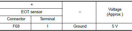
Is the inspection result normal? YES >> GO TO 3.
NO >> GO TO 2.
2.CHECK ENGINE OIL TEMPERATURE SENSOR POWER SUPPLY CIRCUIT
- Turn ignition switch OFF.
- Disconnect ECM harness connector.
- Check the continuity between EOT sensor harness connector and ECM harness connector.
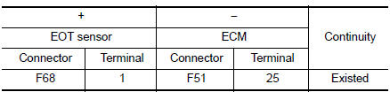
- Also check harness for short to ground.
Is the inspection result normal? YES >> Perform the trouble diagnosis for power supply circuit.
NO >> Repair or replace error-detected parts.
3.CHECK EOT SENSOR GROUND CIRCUIT
- Turn ignition switch OFF.
- Disconnect ECM harness connector.
- Check the continuity between EOT sensor harness connector and ECM harness connector.
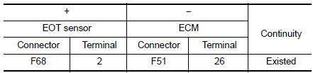
- Also check harness for short to power.
Is the inspection result normal? YES >> GO TO 4.
NO >> Repair or replace error-detected parts.
4.CHECK ENGINE OIL TEMPERATURE SENSOR
Check the engine oil temperature sensor. Refer to EC-279, "Component Inspection".
Is the inspection result normal? YES >> GO TO 5.
NO >> Replace engine oil temperature sensor. Refer to EC-14, "Component Parts Location".
5.CHECK INTERMITTENT INCIDENT
Refer to GI-41, "Intermittent Incident".
>> INSPECTION END
Component Inspection
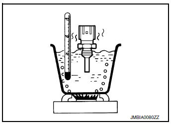
1.CHECK ENGINE OIL TEMPERATURE SENSOR
- Turn ignition switch OFF.
- Disconnect engine oil temperature sensor harness connector.
- Remove engine oil temperature sensor.
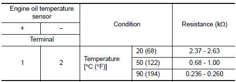
- Check resistance between engine oil temperature sensor terminals by heating with hot water as shown in the figure.
Is the inspection result normal? YES >> INSPECTION END
NO >> Replace engine oil temperature sensor. Refer to EC-14, "Component Parts Location".
 P0196 EOT sensor
DTC Description
DTC DETECTION LOGIC
DTC No.
CONSULT screen terms
(Trouble diagnosis content)
DTC detecting condition
P0196
EOT SENSOR
(Engine oil temperature sensor ra ...
 P0222, P0223 TP sensor
DTC Description
DTC DETECTION LOGIC
DTC No.
CONSULT screen terms
(Trouble diagnosis content)
DTC detecting condition
P0222
TP SEN 1/CIRC-B1
(Throttle/pedal position se ...
Other materials:
System description
COMPONENT PARTS
POWER DOOR LOCK SYSTEM
POWER DOOR LOCK SYSTEM : Component Parts Location
No
Component
Function
1
BCM
Controls the door lock system.
Refer to BCS-7, "BODY CONTROL SYSTEM : Component Parts Location" for
detailed
install ...
P117A air fuel ratio
DTC Description
DTC DETECTION LOGIC
DTC No.
CONSULT screen terms
(Trouble diagnosis content)
DTC detecting condition
P117A
AIR FUEL RATIO B1
(AIR FUEL RATIO B1)
ECM detects a lean/rich air fuel ratio state in any cylinder for a
specified
length of time.
...
Steering wheel
Inspection
STEERING WHEEL AXIAL END PLAY
Check installation conditions of steering gear, front suspension
assembly, axle and steering column.
Check if movement exists when steering wheel is moved up and down,
to the left and right and to the axial
direction.
Steering wh ...
