Nissan Rogue Service Manual: Interior room lamp power supply circuit
Description
Provides the interior room lamp power supply. Also cuts the power supply when the interior room lamp battery saver is activating.
Component Function Check
1.CHECK INTERIOR ROOM LAMP POWER SUPPLY FUNCTION
CONSULT ACTIVE TEST
- Turn power switch ON.
- Turn each interior room lamp ON.
- Map lamp
- Room lamp
- Personal lamps 2nd row (if equipped)
- Luggage room lamp
- Select ÔÇťBATTERY SAVERÔÇŁ of ÔÇťBCMÔÇŁ active test item.
- With operating the test items, check that each interior room lamp turns ON/OFF.
Off : Interior room lamp OFF
On : Interior room lamp ON
Does each interior room lamp turn ON/OFF? YES >> Interior room lamp power supply circuit is normal.
NO >> Refer to INL-46, "Diagnosis Procedure".
Diagnosis Procedure
1.CHECK INTERIOR ROOM LAMP POWER SUPPLY OUTPUT
 CONSULT ACTIVE TEST
- Turn power switch OFF.
- Turn power switch ON.
- Select ÔÇťBATTERY SAVERÔÇŁ of ÔÇťÔÇŁ active test item.
- With operating the test item, check continuity between BCM harness connector and ground.
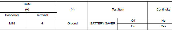
Is the inspection result normal? YES >> GO TO 2.
NO >> Replace BCM. Refer to BCS-75, "Removal and Installation" (with Intelligent Key system) or BCS- 135, "Removal and Installation" (without Intelligent Key system).
2.CHECK INTERIOR ROOM LAMP RELAY SIGNAL OPEN CIRCUIT
- Turn power switch OFF.
- Disconnect the BCM connector and room lamp relay.
- Check continuity between BCM harness connector and room lamp relay harness connector.
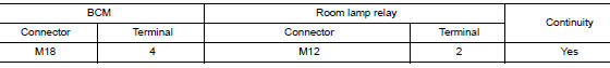
Is the inspection result normal? YES >> GO TO 3.
NO >> Repair or replace harnesses.
3.CHECK INTERIOR ROOM LAMP RELAY POWER SUPPLY CIRCUIT
- Check voltage at room lamp relay harness connector.
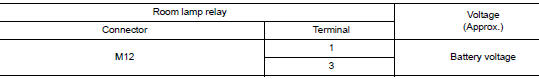
Is the inspection result normal? YES >> GO TO 4.
NO >> Repair or replace harnesses.
4.CHECK INTERIOR ROOM LAMP RELAY POWER SUPPLY OUTPUT
- Reconnect room lamp relay.
- Check voltage at room lamp relay harness connector.
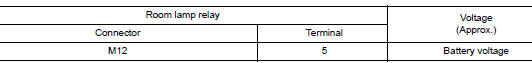
Is the inspection result normal? YES >> GO TO 5.
NO >> Replace room lamp relay.
5.CHECK INTERIOR ROOM LAMP RELAY POWER SUPPLY OUTPUT
- Disconnect he following connectors:
- Room lamp relay M12
- Map lamp assembly R6
- Room lamp R15
- Personal lamps 2nd row R16 (if equipped)
- Vanity mirror lamp LH R14
- Vanity mirror lamp RH R10
- Luggage room lamp B118
- Check continuity between room lamp relay connector M12 and interior room lamp connector in question.
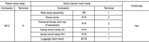
Is the inspection result normal? YES >> GO TO 6.
NO >> Repair or replace harnesses.
6.CHECK INTERIOR ROOM LAMP RELAY POWER SUPPLY OUTPUT SHORT CIRCUIT
Check continuity between room lamp relay and ground.
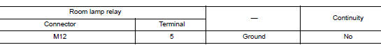
Is the inspection result normal? YES >> Check that each interior lamp has no internal short circuit.
NO >> Repair or replace harnesses.

 Interior room lamp control circuit
Description
Controls each interior room lamp (ground side) by PWM signal.
NOTE:
PWM signal control period is approximately 250 Hz (in the gradual
brightening/dimming).
Component Function Check
...
Other materials:
How to use the remote keyless entry
function
The remote keyless entry function can operate all
door locks using the remote keyless function of
the Intelligent Key. The remote keyless function
can operate at a distance of 33 ft (10 m) away
from the vehicle. The operating distance depends
upon the conditions around the vehicle.
The remot ...
Connector Symbols
Most of connector symbols in wiring diagrams are shown from the terminal
side.
Connector symbols shown from the terminal side are enclosed by
a single line and followed by the direction mark.
Connector symbols shown from the harness side are enclosed by
a double line and foll ...
Does not operate
Description
VDC function, TCS function, ABS function, EBD function, Brake limited slip
differential (BLSD) function, Brake
assist function, hill start assist function or Brake force distribution function
does not operate.
Diagnosis Procedure
CAUTION:
VDC function, TCS function, ABS ...
