Nissan Rogue Service Manual: Shift lock system
Component Function Check
1.CHECK SHIFT LOCK OPERATION (PART 1)
- Turn ignition ON.
- Shift the selector lever to “P” position.
- Attempt to shift the selector lever to any other than position with the brake pedal released.
Can the selector lever be shifted to any other position? YES >> Go to TM-183, "Diagnosis Procedure".
NO >> GO TO 2.
2.CHECK SHIFT LOCK OPERATION (PART 2)
Attempt to shift the selector lever to any other than position with the brake pedal depressed.
Can the selector lever be shifted to any other position? YES >> Inspection End.
NO >> Go to TM-183, "Diagnosis Procedure".
Diagnosis Procedure
Regarding Wiring Diagram information, refer to TM-75, "Wiring Diagram".
1.CHECK STOP LAMP SWITCH
- Ignition switch ON.
- Check voltage between stop lamp switch connector E38 terminal 4 and ground.
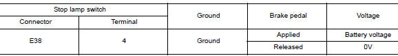
Is the inspection result normal? YES >> GO TO 2.
NO >> GO TO 4.
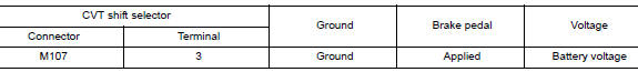
2.CHECK CVT SHIFT SELECTOR
Check voltage between CVT shift selector connector M107 terminal 4 and ground.

Is the inspection result normal? YES >> GO TO 3.
NO >> GO TO 5.
3.CHECK GROUND CIRCUIT
- Ignition switch OFF.
- Disconnect CVT shift selector connector.
- Check continuity between CVT shift selector connector M107 terminal 4 and ground.
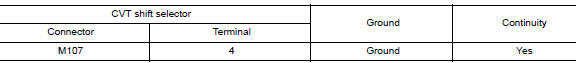
Is the inspection result normal? YES >> Replace CVT shift selector. Refer to TM-194, "Removal and Installation".
NO >> Repair or replace harness.
4.CHECK STOP LAMP SWITCH POWER CIRCUIT
Check voltage between stop lamp switch connector E38 terminal 3 and ground.
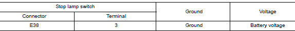
Is the inspection result normal? YES >> Replace stop lamp switch. Refer to BR-20, "Exploded View".
NO >> Repair or replace harness.
5.CHECK CVT SHIFT SELECTOR POWER CIRCUIT
Check voltage between CVT shift selector connector M107 terminal 3 and ground.
Is the inspection result normal? YES >> Replace CVT shift selector. Refer to TM-194, "Removal and Installation".
NO >> Repair or replace harness or connector.
Component Inspection (CVT Shift Selector Assembly)
1.CHECK CVT SHIFT SELECTOR ASSEMBLY (PART 1)
Check continuity between CVT shift selector connector terminals.
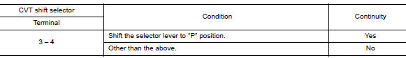
Is the inspection result normal? YES >> GO TO 2.
NO >> Replace CVT shift selector assembly. Refer to TM-194, "Removal and Installation".
2.CHECK CVT SHIFT SELECTOR ASSEMBLY (PART 2)
Apply voltage to terminals of CVT shift selector and check that shift lock solenoid is activated.
CAUTION:
- Connect the fuse between the terminals when applying the voltage.
- Never cause shorting between terminals.
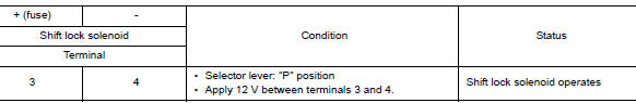
Is the inspection result normal? YES >> Inspection End NO >> Replace CVT shift selector assembly. Refer to TM-194, "Removal and Installation".
Component Inspection (Stop Lamp Switch)
1.CHECK STOP LAMP SWITCH
Check continuity between the stop lamp switch connector terminals.

Is the inspection result normal? YES >> Inspection End.
NO >> Replace stop lamp switch. Refer to BR-20, "Exploded View".
 Shift position indicator circuit
Component Parts Function Inspection
1.CHECK SHIFT POSITION INDICATOR
Start the engine.
Shift selector lever.
Check that the selector lever position and the shift position
...
 Symptom diagnosis
CVT CONTROL SYSTEM
Symptom Table
The diagnosis item number indicates the order of check. Start checking
in the order from 1.
Perform diagnoses of symptom table 1 before symptom table 2 ...
Other materials:
Front seat
DRIVER SIDE
DRIVER SIDE : Exploded View
POWER SEAT
Headrest
Seatback support
Seatback board
Seatback heater (if equipped)
Seatback trim
Seatback pad
Seat cushion outer finisher (RH)
Seat cushion rear finisher
(RH)
Seat cushion inner fini ...
Heating and cooling unit assembly
Exploded View
Steering Member
Heating and cooling unit assembly
Steering member
Bolt
Nut
Automatic Air Conditioning
Wiring harness
Air mix door duct (LH)
Air mix door duct (RH)
Intake housing gasket
Blower motor
Front foot duct (RH)
...
Active trace control
This system senses driving based on the driver’s
steering and acceleration/braking patterns, and
controls brake pressure at individual wheels to
aid tracing at corners and help smooth vehicle
response.
The Active Trace Control can be set to ON (enabled)
or OFF (disabled) through the Vehicl ...
