Nissan Rogue Owners Manual: Instrument panel
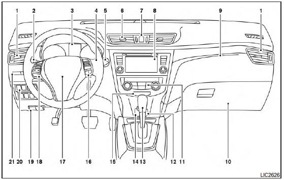
- Vent
- Headlight/fog light (if so equipped)/turn signal switch
- Meters, gauges, warning/indicator lights and Vehicle Information Display
- Windshield wiper/washer switch and rear window wiper/washer switch /Ignition switch (if so equipped)
- Push-button ignition switch (if so equipped)
- Vent
- Hazard warning flasher switch
- Radio /Navigation system* (if so equipped)
- . Front passenger supplemental air bag
- Glove box
- Heater and air conditioning controls
- Power outlet
- Shift lever
- Auxiliary jack /USB port
- Front passenger air bag status light
- Cruise control main/set switches (/Bluetooth Hands-Free Phone System (if so equipped)
- Driver supplemental air bag/Horn (, )
- Control panel and Vehicle Information Display switches
- Hood release /Fuel door release
- Vehicle Dynamic Control (VDC) OFF switch Sport mode switch ECO mode switch (if so equipped) Power liftgate switch (if so equipped) (P.3-28) Power liftgate main switch (if so equipped) Warning systems switch (if so equipped) All-Wheel Drive (AWD) lock switch (if so equipped) Hill descent control switch (if so equipped)
- Instrument brightness control /Twin trip odometer reset switch
*: Refer to the separate Navigation System Owner’s Manual (if so equipped).
Refer to the page number indicated in parentheses for operating details.

 Meters and gauges
Tachometer
Warning/indicator lights
Vehicle Information Display/Odometer/
Twin trip odometer
Speedometer
Fuel gauge
Engine coolant temperature gauge
...
Other materials:
Preparation
Special Service Tool
The actual shape of the tools may differ from those illustrated here.
Tool number
(TechMate No.)
Tool name
Description
—
(J-39570)
Chassis Ear
Locating the noise
—
(J-50397)
NISSAN Squeak and Rattle
Kit
...
Preparation
Special Service Tool
The actual shape of the tools may differ from those illustrated here.
Tool number
(TechMate No.)
Tool name
Description
—
(J-46534)
Trim Tool Set
Removing trim components
Commercial Service Tools
Tool name
...
C1601 battery power supply
DTC Logic
DTC DETECTION LOGIC
DTC
Display item
Malfunction detected condition
Possible cause
C1601
BATTERY VOLT
When a power supply voltage to the EPS control unit
is maintained at 18.2 V or more or at less than 9 V
continuously for five second ...
