Nissan Rogue Owners Manual: Installing front license plate
Installing front license plate
Use the following steps to mount the front license plate:
Before mounting the license plate, confirm that the following parts are enclosed in the plastic bag:
- License plate bracket
- License plate bracket (J-nut) screws x 2
- License plate screws x 2
- Screw grommets x 2
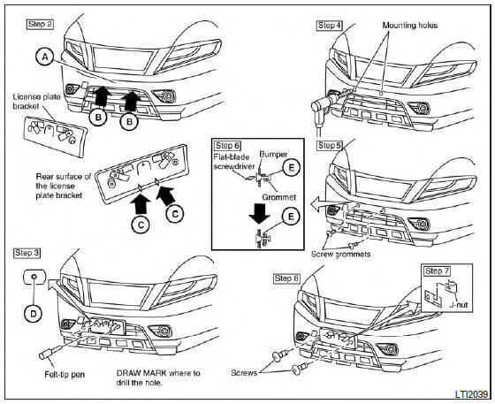
- Park the vehicle on flat, level ground.
- Locate the center position A as illustrated.
Line up the license plate bracket under the top of the front bumper B with the tabs C .
Hold the license plate bracket in place.
- Mark the center of the hole D with a felt-tip pen.
- Carefully drill two pilot holes using a 0.39 in (10 mm) drill bit at the marked locations. (Be sure that the drill only goes through the bumper fascia.)
- Insert the grommets into the holes in the bumper fascia.
- Insert a small flat-bladed screwdriver into the grommet hole to turn the threaded part of the grommet 90° E .
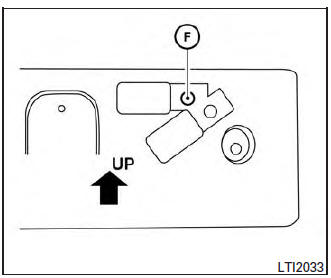
Mark the center of the hole F on both sides with a felt-tip pen. Remove the bracket from the bumper, and then open 0.79 in (20 mm) diameter holes on the bumper using the marks F as a center.
- Insert a J-nut into the license plate bracket before placing the license plate bracket on the fascia.
- Install the license plate bracket with screws.
- Install the license plate with bolts that are no longer than 0.55 in (14 mm).
 Vehicle identification
Vehicle identification number (VIN) plate
The vehicle identification number (VIN) plate is
located as shown. This number is the identification
for your vehicle and is used in the vehicle
regi ...
 Vehicle loading information
WARNING
It is extremely dangerous to ride
in a cargo area inside a vehicle. In
a collision, people riding in these
areas are more likely to be seriously
injured or kil ...
Other materials:
Periodic maintenance
IN-CABIN MICROFILTER
Removal and Installation
REMOVAL
Release the tab and remove the in-cabin microfilter cover (1)
from under the RH side of the instrument panel.
CAUTION:
Use care when lifting up on the tab to avoid damaging it.
Remove the in-cabin microfilter (2).
CAUT ...
Preparation
Special Service Tool
The actual shape of the tools may differ from those illustrated here.
Tool number
(TechMate No.)
Tool name
Description
—
(J-46534)
Trim Tool Set
Removing trim components
...
C1769 configuration setting
DTC Description
This procedure must be performed:
After replacement of BCM.
DTC DETECTION LOGIC
DTC
Display Item
Malfunction detected condition
C1769
CONFIG SETTING
(Configuration setting)
Tire air pressure monitoring system configuration cannot be
p ...
