Nissan Rogue Service Manual: Front wiper does not operate
Description
The front wiper does not operate under any operation conditions.
Diagnosis Procedure
Regarding Wiring Diagram information, refer to WW-22, "Wiring Diagram".
1. CHECK WIPER RELAY OPERATION
 CONSULT ACTIVE TEST
- Select FR WIPER of BCM (WIPER) active test item.
- Check front wiper operation.
LO : Front wiper LO operation
HI : Front wiper HI operation
OFF : Front wiper stop
Is the inspection result normal? YES >> GO TO 5.
NO >> GO TO 2.
2. CHECK FRONT WIPER MOTOR FUSE
Refer to WW-35, "Diagnosis Procedure".
Is the fuse blown? YES >> Replace the fuse after repairing the affected circuit.
NO >> GO TO 3.
3. CHECK FRONT WIPER MOTOR GROUND CIRCUIT
Refer to WW-42, "Diagnosis Procedure".
Is the inspection result normal? YES >> GO TO 4.
NO >> Repair or replace harness.
4. CHECK FRONT WIPER MOTOR OUTPUT VOLTAGE
- Turn the ignition switch ON.
- With CONSULT, select FRONT WIPER of IPDM E/R ACTIVE TEST item.
- Check voltage between IPDM E/R harness connector and ground while wipers are operating.
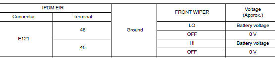
Is the inspection result normal? YES >> Replace front wiper motor. Refer to WW-67, "Removal and Installation".
NO >> Replace IPDM E/R. Refer to PCS-35, "Removal and Installation".
5. CHECK FRONT WIPER REQUEST SIGNAL INPUT
- With CONSULT, select FR WIP REQ in DATA MONITOR of IPDM E/R.
- Switch the front wiper switch to HI and LO.
- Check the status of FR WIP REQ while operating the switch.
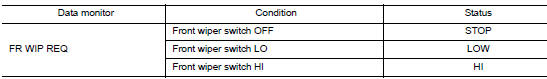
Is the inspection result normal? YES >> Replace IPDM E/R. Refer to PCS-35, "Removal and Installation" .
NO >> GO TO 6.
6. CHECK COMBINATION SWITCH (WIPER AND WASHER SWITCH)
Check combination switch (wiper and washer switch). Refer to WW-45, "Component Inspection".
Is the inspection result normal? YES >> Replace BCM. Refer to BCS-75, "Removal and Installation" (with Intelligent Key system) or BCS- 135, "Removal and Installation" (without Intelligent Key system).
NO >> Repair or replace the applicable parts.
 Wiper and washer system symptoms
Symptom Table
CAUTION:
Perform the self-diagnosis with CONSULT before performing the diagnosis by
symptom. Perform the
diagnosis by DTC if DTC is detected.
...
 Normal operating condition
Description
FRONT WIPER PROTECTION FUNCTION
IPDM E/R detects front wiper stop position by a front wiper stop position
signal.
When a front wiper stop position signal is in the conditions listed ...
Other materials:
Jump starting
To start your engine with a booster battery, the
instructions and precautions below must be followed.
WARNING
If done incorrectly, jump starting can
lead to a battery explosion, resulting in
severe injury or death. It could also
damage your vehicle.
Explosive ...
How to erase permanent DTC
Description
OUTLINE
When a DTC is stored in ECM
When a DTC is stored in ECM and MIL is ON, a permanent DTC is erased with MIL
shutoff if the same malfunction
is not detected after performing the driving pattern for MIL shutoff three times
in a raw.
*1: When the same malfunction is detecte ...
Front door finisher
Exploded View
Front door
Front door pull handle bracket
Front door pull handle
Front power window switch (RH)
finisher
Front door inside handle finisher
Front door finisher
Clip
Pawl
REMOVAL
NOTE:
LH shown, RH similar.
Release pawls using a suitable tool (A) from ...
