
Nissan Rogue Service Manual: Front seat
DRIVER SIDE
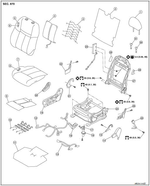
DRIVER SIDE : Exploded View
POWER SEAT
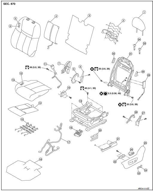
- Headrest
- Seatback support
- Seatback board
- Seatback heater (if equipped)
- Seatback trim
- Seatback pad
- Seat cushion outer finisher (RH)
- Seat cushion rear finisher (RH)
- Seat cushion inner finisher (RH)
- Seat slide finisher (RH)
- Seat belt buckle
- Seat cushion trim
- Seat cushion pad
- Seat cushion heater (if equipped)
- Seat cushion support
- Seat cushion silencer
- Seat harness
- Seat harness bracket
- Seat cushion frame
- Seat slide finisher bracket (LH)
- Seat slide finisher (LH)
- Power seat switch
- Seat slide knob
- Side recline knob
- Seat cushion outer finisher (LH)
- Lumbar support switch
- Seat cushion rear finisher (LH)
- Seat cushion inner finisher (LH)
- Side air bag module (not serviceable)
- Seatback bracket (LH)
- Seatback frame
- Seatback bracket (RH)
- Headrest holder (locked)
- Headrest holder (free)
MANUAL SEAT
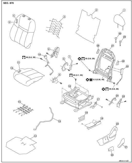
- Headrest
- Seatback board
- Seatback support
- Seatback trim
- Seatback pad
- Seat cushion outer finisher
- Seat cushion rear finisher (RH)
- Seat cushion inner finisher (RH)
- Seat slide finisher (RH)
- Seat belt buckle
- Seat cushion trim
- Seat cushion pad
- Seat cushion support
- Seat cushion silencer
- Seat harness
- Seat cushion frame
- Recline switch
- Seat slide finisher bracket (LH)
- Seat slide finisher (LH)
- Lift lever
- Recline lever
- Seat cushion outer finisher (LH)
- Seat cushion rear finisher (LH)
- Seat cushion inner finisher (LH)
- Side air bag module (not serviceable)
- Seatback bracket (LH)
- Seatback frame
- Seatback bracket (RH)
- Headrest holder (locked)
- Headrest holder (free)
DRIVER SIDE : Removal and Installation
REMOVAL
WARNING: Do not leave any objects (screwdrivers, tools, etc.) on the seat during seatback repair. It can lead to personal injury if the side air bag module should accidentally deploy.
CAUTION:
- When removing or installing the seat trim, handle it carefully to keep dirt out and to avoid damage.
- When checking the power seat circuit for continuity using a circuit tester, do not confuse its connector with the side air bag module connector. Such an error may cause the air bag module to deploy.
- Do not drop, tilt, or bump the side air bag module while installing the seat. Always handle it with care.
- After front side air bag module inflates, the front seatback assembly must be replaced.
- When removing and installing the seat, use shop cloths to protect components from damage.
- Before removing the front seat, turn the ignition switch OFF, disconnect both battery cables then wait at least three minutes.
- Slide the seat to the full rearward position.
- Disconnect negative and positive battery terminals, then wait at least three minutes. Refer to PG-77, "Removal and Installation" (power seat only).
- Disconnect harness connector from side air bag module.
- Remove front bolts.
- Connect negative and positive battery terminals, then slide the seat to the full forward position. Refer to PG-77, "Removal and Installation" (power seat only).
- Slide the seat to the full forward position.
- Disconnect negative and positive battery terminals, then wait at least three minutes. Refer to PG-77, "Removal and Installation" (power seat only).
- Remove rear bolts.
- Tilt the seat rearward and disconnect the harness connectors from
the seat.
NOTE: Take note of harness routing and attachment locations for correct installation.
- Remove the seat from the vehicle.
INSTALLATION
Installation is in the reverse order of removal.
CAUTION: Make sure that the seat harness or the floor carpet is not damaged during installation.
NOTE:
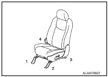
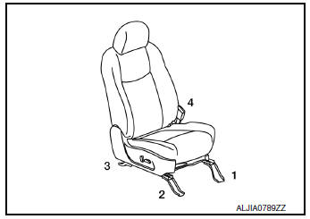
- When installing the front seat (LH), tighten the bolts in the order shown.
- Tighten the seat bolts to specification. Refer to SE-29, "DRIVER SIDE : Exploded View".
PASSENGER SIDE
PASSENGER SIDE : Exploded View
POWER SEAT
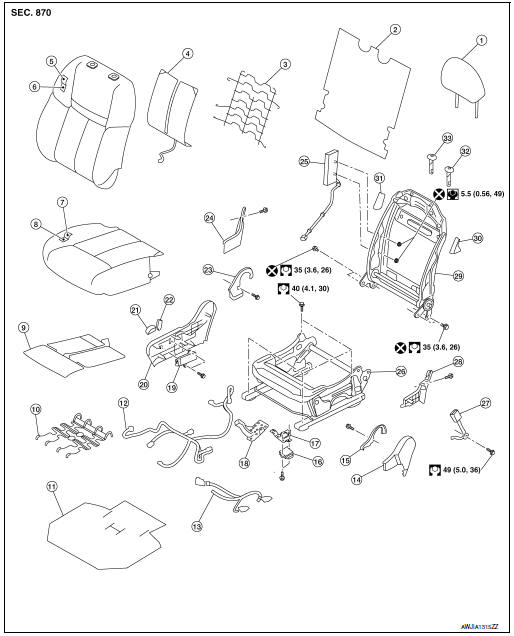
- Headrest
- Seatback board
- Seatback support
- Seatback heater
- Seat cushion trim
- Seat cushion pad
- Seat cushion trim
- Seat cushion pad
- Seat cushion heater
- Seat cushion support
- Seat cushion silencer
- Seat harness
- Occupant classification system harness
- Seat cushion outer finisher (LH)
- Seat cushion inner finisher (LH)
- Occupant classification system control unit
- Occupant classification system bracket
- Wiring harness bracket
- Power seat switch
- Seat cushion outer finisher (RH)
- Seat slide knob
- Seat recline knob
- Seat cushion inner finisher (RH)
- Seat cushion rear finisher (RH)
- Side air bag module (not serviceable)
- Seat cushion frame
- Seat belt buckle
- Seat cushion rear finisher (LH)
- Seatback frame
- Seatback bracket (LH)
- Seatback bracket (RH)
- Headrest holder (locked)
- Headrest holder (free)
MANUAL SEAT
- Headrest
- Seatback board
- Seatback support
- Seatback heater (if equipped)
- Seatback trim
- Seatback pad
- Seat cushion trim
- Seat cushion pad
- Seat cushion heater (if equipped)
- Seat cushion support
- Seat cushion silencer
- Seat harness
- Occupant classification system harness
- Seat cushion outer finisher (LH)
- Seat cushion inner finisher (LH)
- Occupant classification system control unit
- Occupant classification system control unit bracket
- Wiring harness bracket
- Seat cushion outer finisher
- Recline lever
- Seat cushion inner finisher (RH)
- Seat cushion rear finisher (RH)
- Side air bag module (not serviceable)
- Seat cushion frame
- Seat belt buckle
- Seat cushion rear finisher (LH)
- Seatback frame
- Seatback bracket (LH)
- Seatback bracket (RH)
- Headrest holder (free)
- Headrest holder (locking)
PASSENGER SIDE : Removal and Installation
REMOVAL
WARNING: Do not leave any objects (screwdrivers, tools, etc.) on the seat during seatback repair. It can lead to personal injury if the side air bag module should accidentally deploy.
CAUTION:
- When removing or installing the seat trim, handle it carefully to keep dirt out and to avoid damage.
- When checking the power seat circuit for continuity using a circuit tester, do not confuse its connector with the side air bag module connector. Such an error may cause the air bag module to deploy.
- Do not drop, tilt, or bump the side air bag module while installing the seat. Always handle it with care.
- After front side air bag module inflates, the front seatback assembly must be replaced.
- When removing and installing the seat, use shop cloths to protect components from damage.
- Before removing the front seat, turn the ignition switch OFF, disconnect both battery cables then wait at least three minutes.
- Slide the seat to the full rearward position.
- Disconnect negative and positive battery terminals, then wait at least three minutes. Refer to PG-77, "Removal and Installation" (power seat only).
- Disconnect harness connector from side air bag module.
- Remove front bolts.
- Connect negative and positive battery terminals, then slide the seat to the full forward position. Refer to PG-77, "Removal and Installation" (power seat only).
- Slide the seat to the full forward position.
- Disconnect negative and positive battery terminals, then wait at least three minutes. Refer to PG-77, "Removal and Installation" (power seat only).
- Remove rear bolts.
- Tilt the seat rearward and disconnect the harness connectors from
the seat.
NOTE: Take note of harness routing and attachment locations for correct installation.
- Remove the seat from the vehicle.
INSTALLATION
Installation is in the reverse order of removal.
WARNING:
- Perform additional services when installing front passenger seat. Refer to SRC-42, "ADDITIONAL SERVICE WHEN REPLACING CONTROL UNIT : Description".
- Zero point reset must be performed every time the front passenger seat is removed from the vehicle.
- Zero point reset is done after the front passenger seat is installed in vehicle and all bolts are tightened to specification.
CAUTION: Make sure that the seat harness or the floor carpet is not damaged during installation.
NOTE:
- When installing the front seat (RH), tighten the bolts in the order shown.
- Tighten the seat bolts to specification. Refer to SE-33, "PASSENGER SIDE : Exploded View".

 Second row seats
Exploded View
RH SEAT
Headrest
Seatback upper luggage
board
Seatback luggage board
Seatback trim
Seatback pad
Recline release cable
Seat cushion trim
Fol ...
Other materials:
U1000 CAN COMM circuit
Description
CAN (Controller Area Network) is a serial communication system for real time
application. It is an on-vehicle
multiplex communication system with high data communication speed and excellent
error detection ability.
Many electronic control units are equipped into vehicles, and ea ...
The fuel gauge does not move
Description
Fuel gauge does not move from a certain position.
Diagnosis Procedure
1.CONDUCTING THE COMBINATION METER SELF-DIAGNOSIS MODE
Perform the self-diagnosis mode of combination meter, and then check that the
fuel gauge operates normally.
Refer to MWI-19, "Description".
I ...
Diagnosis system (BCM) (without intelligent key system)
COMMON ITEM
COMMON ITEM : CONSULT Function (BCM - COMMON ITEM)
APPLICATION ITEM
CONSULT performs the following functions via CAN communication with BCM.
Direct Diagnostic Mode
Description
Ecu Identification
The BCM part number is displayed.
Self Diagnostic ...
