Nissan Rogue Service Manual: ECU diagnosis information
AUDIO UNIT
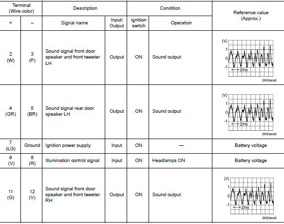
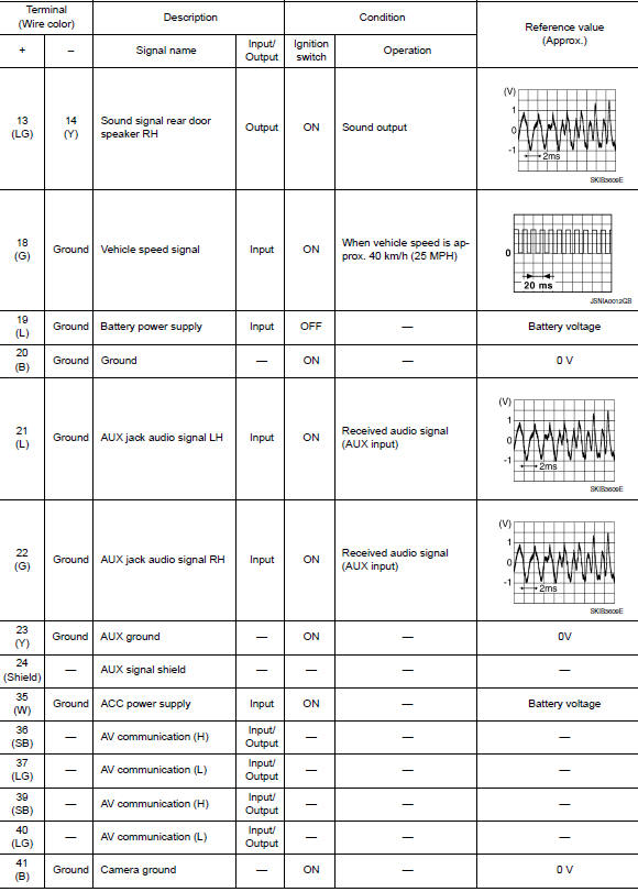
Reference Value
TERMINAL LAYOUT

PHYSICAL VALUES

 System description
COMPONENT PARTS
Component Parts Location
Center of back door
No.
Component
Function
1
Rod antenna
Refer to AV-14, "Rod Antenna, Antenna Amp., S ...
 Wiring diagram
DISPLAY AUDIO
Wiring Diagram
...
Other materials:
Diagnosis system (EPS control unit)
CONSULT Function
FUNCTION
CONSULT can display each diagnostic item using the diagnostic test modes
shown following
Diagnostic test mode
Function
ECU identification
The part number stored in the control unit can be read.
Self diagnostic result
Self-diagnosti ...
When traveling or registering your vehicle in
another country
When planning to drive your NISSAN vehicle
in another country, you should first find
out if the fuel available is suitable for your vehicle’s
engine.
Using fuel with an octane rating that is too low
may cause engine damage. All gasoline vehicles
must be operated with unleaded gasoline. The ...
Removal and installation
FRONT CAMERA
Exploded View
Front grille
Front camera
Removal and Installation
REMOVAL
Remove the front grille. Refer to EXT-23, "Removal and
Installation".
Remove screws and front camera.
INSTALLATION
Installation is in the reverse order of re ...
