Nissan Rogue Service Manual: ECU diagnosis information
BCM, IPDM E/R
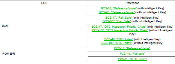
List of ECU Reference
 System description
COMPONENT PARTS
Component Parts Location
Right rear wheel area
Instrument panel
Engine compartment
Left side of instrument panel (view
with trim panel removed)
No.
...
 Wiring diagram
HEADLAMP
Wiring Diagram
DAYTIME LIGHT SYSTEM
Wiring Diagram
AUTO LIGHT SYSTEM
Wiring Diagram
FRONT FOG LAMP SYST ...
Other materials:
Inside mirror
Exploded View
MANUAL ANTI-DAZZLING
Windshield glass
Mirror base
Inside mirror
AUTO ANTI-DAZZLING
Windshield glass
Mirror base
Inside mirror
Inside mirror finisher
Harness connector
Bolt
Removal and Installation
MANUAL ANTI-DAZZLING
Removal ...
Bluetooth® streaming audio with Navigation
System
If you have a compatible Bluetooth® audio device
that is capable of playing audio files, the
device can be connected to the vehicle’s audio
system so that the audio files on the device play
through the vehicle’s speakers.
Connecting Bluetooth® audio
To connect your Bluetooth® audio ...
How to use the [ ] button
For additional information, refer to the separate
Navigation System Owner’s Manual regarding
the “SiriusXM® Travel Link”, and “Traffic” features.
For additional information, refer to “Nissan-
ConnectSM with Mobile Apps” in this section
regarding “My Apps” key.
For ad ...
