Nissan Rogue Service Manual: ECU diagnosis information
A/C AUTO AMP.
Reference Value
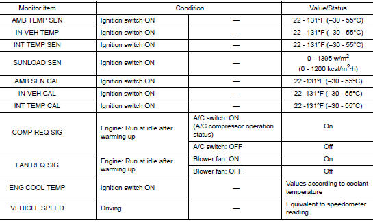
VALUES ON THE DIAGNOSIS TOOL
TERMINAL LAYOUT
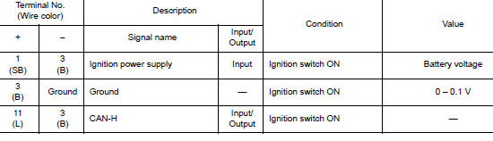
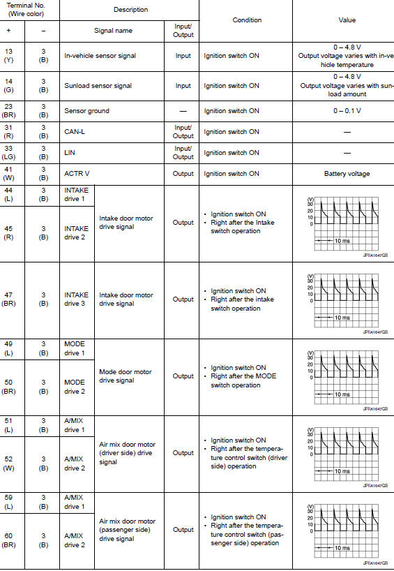
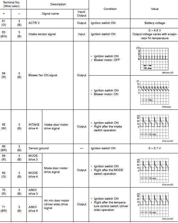
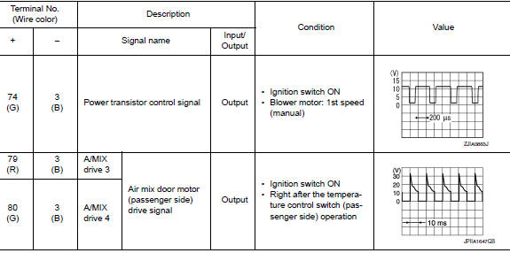
PHYSICAL VALUES
DTC Inspection Priority Chart
If some DTCs are displayed at the same time, perform inspections one by one based on the following priority chart.
|
Priority |
Detected items (DTC) |
| 1 |
|
| 2 |
|
DTC Index
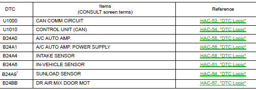

*: Perform self-diagnosis under direct sunlight. When performing indoors, aim a light (more than 60 W) at sunload sensor, otherwise selfdiagnosis reports an error even though the sunload sensor is functioning normally.
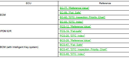
ECM, IPDM E/R, BCM
List of ECU Reference
 System description
Component Part Location
RH side of engine compartment
RH front of vehicle (view with front
bumper fascia removed)
LH front of vehicle (view with front
bumper fascia remove ...
 Wiring diagram
AUTOMATIC AIR CONDITIONING SYSTEM
Wiring Diagram
...
Other materials:
P0171 fuel injection system function
DTC Description
DTC DETECTION LOGIC
With the Air/Fuel Mixture Ratio Self-Learning Control, the actual mixture
ratio can be brought closely to the
theoretical mixture ratio based on the mixture ratio feedback signal from the
A/F sensors 1. The ECM calculates
the necessary compensation to corr ...
Preparation
Special Service Tool
The actual shape of the tools may differ from those illustrated here.
Tool number
(TechMate No.)
Tool name
Description
—
(J-39570)
Chassis Ear
Locating the noise
—
(J-50397)
NISSAN Squeak and Rattle
Kit
...
Sunglasses holder
Sunglasses holder
To open the sunglasses holder 1 , push and
release.
Only store one pair of sunglasses in the holder.
WARNINGKeep the sunglasses holder closed while
driving to prevent an accident.
CAUTION
Do not use for anything other than
sung ...
