Nissan Rogue Service Manual: Diagnosis and repair work flow
Work Flow
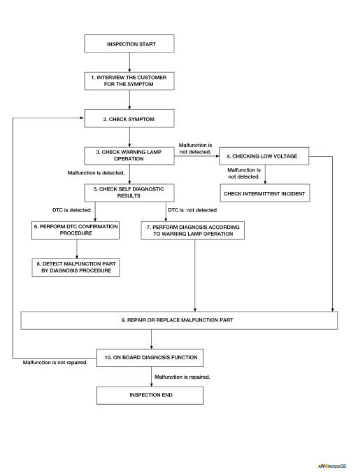
OVERALL SEQUENCE
DETAILED FLOW
1.INTERVIEW THE CUSTOMER FOR THE SYMPTOM
Interview the customer for the symptom (the condition and the environment when the incident/malfunction occurs).
>> GO TO 2.
2.CHECK SYMPTOM
Check the symptom from the customer information.
>> GO TO 3.
3.CHECK WARNING LAMP OPERATION
Check air bag warning lamp operation in the user mode.
Are any malfunction detected? YES >> GO TO 5.
NO >> GO TO 4.
4.CHECK LOW VOLTAGE
Check low voltage with CONSULT.
Are any malfunction detected? YES >> GO TO 9.
NO >> Check intermittent incident. Refer to GI-41, "Intermittent Incident".
5.CHECK SELF DIAGNOSTIC RESULTS
Check self diagnostic result with CONSULT or diagnosis mode.
If it is impossible to switch to diagnosis mode, follow the same procedure that DTC is not detected.
NOTE: Perform the following procedure if DTC is detected.
- Record DTC (Print them out with CONSULT.)
- Erase self diagnostic result.
- Study the relationship between the malfunction that DTC or air bag warning lamp indicates and the symptom that the customer describes.
- Check related service bulletins for information.
Is DTC detected? YES >> GO TO 6.
NO >> GO TO 7.
6.PERFORM DTC CONFIRMATION PROCEDURE
Perform DTC CONFIRMATION PROCEDURE for the DTC.
>> GO TO 8.
7.PERFORM DIAGNOSIS ACCORDING TO WARNING LAMP OPERATION
- Check air bag warning lamp operation in the user mode.
- Perform Diagnosis Procedure for the air bag warning lamp operation.
>> GO TO 9.
8.DETECT MALFUNCTIONING PART BY DIAGNOSTIC PROCEDURE
Inspect according to Diagnostic Procedure of the DTC.
>> GO TO 9.
9.REPAIR OR REPLACE THE MALFUNCTION PART
Repair or replace the malfunctioning part.
>> GO TO 10.
10.ON BOARD DIAGNOSIS FUNCTION
Check self diagnostic result and air bag warning lamp operation in the user mode.
Is the malfunction repaired? YES >> Inspection End.
NO >> GO TO 2.
 Basic inspection
...
 Inspection and adjustment
ADDITIONAL SERVICE WHEN REPLACING CONTROL UNIT
ADDITIONAL SERVICE WHEN REPLACING CONTROL UNIT : Description
When replacing the occupant classification system control unit, perform
zero point r ...
Other materials:
Washer switch
Description
Washer switch is integrated with the combination switch.
Combination switch (wiper and washer switch) switches polarity
between front washer operating and rear
washer operating to supply power and ground to the front and rear washer
motor.
Component Inspection
...
Electrical load signal
Description
The electrical load signal (Headlamp switch signal, rear window defogger
switch signal, etc.) is transferred via
the CAN communication.
Component Function Check
1.CHECK REAR WINDOW DEFOGGER SWITCH FUNCTION
Turn ignition switch ON.
Connect CONSULT and select “DAT ...
Preparation
Special Service Tool
The actual shape of the tools may differ from those illustrated here.
Tool number
(TechMate No.)
Tool name
Description
KV991J0070
(J-45695-A)
Coolant refill tool
Refilling engine cooling system
Commercial Service Too
...
