Nissan Rogue Service Manual: System
System Diagram
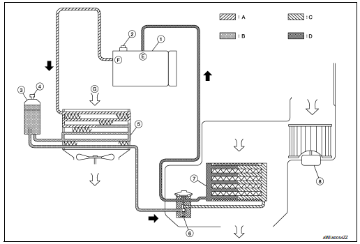
- Compressor
- Pressure relief valve
- Liquid tank
- Refrigerant pressure sensor
- Condenser
- Expansion valve
- Evaporator
- Blower motor
- High-pressure gas
- High-pressure liquid
- Low-pressure liquid
- Low-pressure gas
- Suction port
- Discharge port
- Outside air
System Description
REFRIGERANT CYCLE
Refrigerant Flow
The refrigerant from the compressor flows through the condenser and liquid tank, evaporator, and returns to the compressor. The refrigerant evaporation in the evaporator is controlled by an expansion valve.
Freeze Protection
To prevent evaporator from freezing up, the evaporator air temperature is monitored and the voltage signal to the A/C auto amp. makes the A/C relay go OFF and stop the compressor.
REFRIGERANT SYSTEM PROTECTION
Refrigerant Pressure Sensor
- The refrigerant system is protected against excessively high or low pressures by the refrigerant pressure sensor, located on the liquid tank. The refrigerant pressure sensor detects the pressure inside the refrigerant line and sends the voltage signal to the ECM if the system pressure rises above or falls below the specifications.
- ECM turns the A/C relay to OFF and stops the compressor when the high-pressure side detected by refrigerant pressure sensor to have the following conditions:
- Approximately 3,120 kPa (31.8 kg/cm2, 452 psi) or more (Engine speed is 1,500 rpm or more.)
- Approximately 2,740 kPa (27.9 kg/cm2, 397 psi) or more (Engine speed is less than 1,500 rpm.)
- Approximately 120 kPa (1.2 kg/cm2, 17 psi) or less
Pressure Relief Valve
The refrigerant system is also protected by a pressure relief valve, located in the rear head of the compressor.
The release port on the pressure relief valve automatically opens and releases refrigerant into the atmosphere when the pressure of refrigerant in the system increases to an unusual level [more than 3,800 kPa (38.8 kg/ cm2, 551 psi)].
 Component parts
Component Parts Location
Condenser
Compressor
Refrigerant pressure sensor
Liquid tank
Expansion valve
Evaporator
Component Description
Component
Description ...
 Basic inspection
DIAGNOSIS AND REPAIR WORKFLOW
Workflow
OVERALL SEQUENCE
DETAILED FLOW
1.INTERVIEW CUSTOMER
Interview the customer to obtain as much information as possible about the
conditions and environm ...
Other materials:
B0092 rear side air bag satellite sensor LH
Description
DTC B0092 REAR SATELLITE SENSOR LH
The rear side air bag satellite sensor LH is wired to the air bag diagnosis
sensor unit. The air bag diagnosis
sensor unit will monitor the rear side air bag satellite sensor LH for internal
failures and its circuits for communication
errors.
P ...
The steering switches are inoperative
Description
One or more of the steering switches to control the information display are
inoperative.
Diagnosis Procedure
1.CHECK STEERING SWITCH CIRCUIT
Check steering switch circuit. Refer to MWI-69, "Diagnosis Procedure".
Is the inspection result normal?
YES >> GO TO 2.
...
Malfunction indicator lamp
Component Function Check
1.CHECK MIL FUNCTION
Turn ignition switch ON.
Check that MIL illuminates.
Is the inspection result normal?
YES >> INSPECTION END
NO >> Proceed to EC-476, "Diagnosis Procedure".
Diagnosis Procedure
1.CHECK DTC
Check that DTC UX ...
