
Nissan Rogue Service Manual: Component parts
Component Parts Location
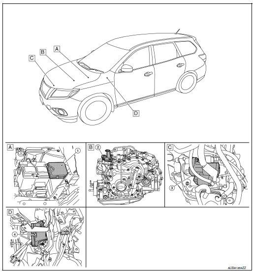
- Engine room (RH)
- View with transmission removed
- View with engine and transmission removed
- Behind instrument panel (LH)
| No. | Component part | Description |
| 1 | IPDM E/R | CPU inside IPDM E/R operates the starter relay when the ignition switch is in the start position. |
| 2 | Transmission range switch | Transmission range switch supplies power to the starter relay and starter control relay inside the IPDM E/R when the selector lever is shifted to the P (Park) or N (Neutral) position. |
| 3 | Starter motor | The starter motor plunger closes and the motor is supplied with battery power, which in turn cranks the engine, when the S terminals supplied with electric power. |
| 4 | BCM | BCM controls the starter relay inside IPDM E/R. |

 System
System Description
The starter motor plunger closes and provides a closed circuit between the
battery and the starter motor. The
starter motor is grounded to the cylinder block. With power and gro ...
Other materials:
Camshaft
Exploded View
Camshaft position sensor (INT)
O-ring
Camshaft brackets (INT)
Camshaft brackets (EXH)
Camshaft (INT)
O-ring
Camshaft bracket (No. 1)
Camshaft sprocket (INT)
Front cover (partial view)
Valve timing control cover O-rings
(INT)
V ...
Interior room lamp control circuit
Description
Controls each interior room lamp (ground side) by PWM signal.
NOTE:
PWM signal control period is approximately 250 Hz (in the gradual
brightening/dimming).
Component Function Check
CAUTION:
Before performing the diagnosis, check that the following is normal.
Interior ro ...
Symptom diagnosis
PUSH-BUTTON IGNITION SWITCH DOES NOT OPERATE
Description
Check that vehicle Operating Conditions are as listed in “Conditions of
Vehicle� below before starting Diagnosis
Procedure. Make sure to check each symptom in Diagnosis Procedure.
NOTE:
The engine start function, door lock functio ...
