Nissan Rogue Service Manual: C1197 vacuum sensor
DTC Logic
DTC DETECTION LOGIC
| DTC | Display Item | Malfunction detected condition | Possible causes |
| C1197 | VACUUM SENSOR | When a malfunction is detected in vacuum sensor. |
|
DTC CONFIRMATION PROCEDURE
1.CHECK SELF-DIAGNOSTIC RESULT
 With CONSULT.
- Turn the ignition switch ON.
- Perform self-diagnostic result.
Is DTC C1197 detected? YES >> Proceed to diagnosis procedure. Refer to BRC-105, "Diagnosis Procedure".
NO >> Inspection End.
Diagnosis Procedure
Regarding Wiring Diagram information, refer to BRC-57, "Wiring Diagram".
1.CHECK BRAKE BOOSTER
- Turn the ignition switch OFF.
- Check brake booster. Refer to BR-10, "Inspection".
Is the inspection result normal? YES >> GO TO 2.
NO >> Replace brake booster. Refer to BR-30, "Removal and installation".
2.CHECK VACUUM PIPING
Check vacuum piping. Refer to BR-32, "Exploded View".
Is the inspection result normal? YES >> GO TO 3.
NO >> Replace vacuum piping. Refer to BR-32, "Removal and Installation".
3.CHECK VACUUM SENSOR CIRCUIT
- Disconnect vacuum sensor harness connector.
- Disconnect ABS actuator and electric unit (control unit) harness connector.
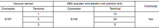
- Check continuity between vacuum sensor harness connector and ABS actuator and electric unit (control unit) harness connector.
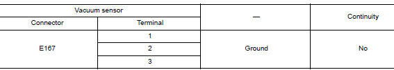
- Check continuity between vacuum sensor harness connector and ground.
Is the inspection result normal? YES >> GO TO 4.
NO >> Repair or replace malfunctioning components.
4.CHECK TERMINAL
- Check vacuum sensor pin terminals for damage or loose connection with harness connector.
- Check ABS actuator and electric unit (control unit) pin terminals for damage or loose connection with harness connector.
Is the inspection result normal? YES >> GO TO 5.
NO >> Repair or replace malfunctioning components.
5.REPLACE VACUUM SENSOR
 With CONSULT
- Connect ABS actuator and electric unit (control unit) harness connector.
- Replace vacuum sensor. Refer to BR-30, "Exploded View".
CAUTION: Always replace brake booster because vacuum sensor cannot be disassembled.
- Erase self-diagnosis result for “ABS”.
- Turn the ignition switch OFF.
- Start engine.
- Perform self-diagnosis for “ABS”.
Is DTC “C1197” detected? YES >> Replace ABS actuator and electric unit (control unit). Refer to BRC-136, "Removal and Installation".
NO >> Inspection End.
 C1170 variant coding
DTC Logic
DTC DETECTION LOGIC
DTC
Display Item
Malfunction detected condition
Possible causes
C1170
VARIANT CODING
When the information in ABS actuator and electric
...
 C1198 vacuum sensor
DTC Logic
DTC DETECTION LOGIC
DTC
Display Item
Malfunction detected condition
Possible causes
C1198
VACUUM SEN CIR
When an open circuit is detected in vacuum ...
Other materials:
Unit disassembly and assembly
TORQUE CONVERTER AND CONVERTER HOUSING OIL SEAL
Exploded View
Torque converter
O-ring
Converter housing oil seal
Transaxle assembly
: Always replace after every
disassembly.
: Apply CVT fluid
Disassembly
Remove transaxle assembly. Refer to TM-220, "Removal and Instal ...
Windshield wiper and washer switch
WARNINGIn freezing temperatures the washer solution
may freeze on the window and obscure
your vision which may lead to an
accident. Warm the window with the defroster
before you wash the window.
CAUTION
Do not operate the washer continuously
for ...
P0461 fuel level sensor
DTC Description
DTC DETECTION LOGIC
Driving long distances naturally affect fuel gauge level.
This diagnosis detects the fuel gauge malfunction of the gauge not moving even
after a long distance has
been driven.
DTC No.
CONSULT screen terms
(Trouble diagnosis content)
DTC de ...
