Nissan Rogue Service Manual: C1101, C1102, C1103, C1104 wheel sensor
DTC Logic
DTC DETECTION LOGIC
| DTC | Display Item | Malfunction detected condition | Possible causes |
| C1101 | RR RH SENSOR-1 |
|
|
| C1102 | RR RH SENSOR-1 |
|
|
| C1103 | RR RH SENSOR-1 |
|
|
| C1104 | FR LH SENSOR-1 |
|
DTC CONFIRMATION PROCEDURE
1.CHECK SELF-DIAGNOSTIC RESULT
 With CONSULT.
- Start engine and drive vehicle at approximately 21 km/h (13 MPH) or more for approximately 5 minutes.
- Perform self-diagnostic result.
Is DTC C1101, C1102, C1103 or C1104 detected? YES >> Proceed to diagnosis procedure. Refer to BRC-74, "Diagnosis Procedure".
NO >> Inspection End.
Diagnosis Procedure
Regarding Wiring Diagram information, refer to BRC-57, "Wiring Diagram".
1.CONFIRM DTC
With CONSULT
- Perform self-diagnostic result of “ABS” and record all active DTCs.
- Clear all DTCs.
- Perform DTC confirmation procedure. Refer to BRC-74, "DTC Logic".
Does DTC C1101, C1102, C1103 or C1104 reset? YES >> GO TO 2.
NO >> Refer to GI-41, "Intermittent Incident".
2.INSPECT WHEEL SENSOR
Inspect the suspect wheel sensor for damage or deformation.
Is the inspection result normal? YES >> GO TO 3.
NO >> Repair or replace as necessary.
3.HARNESS AND CONNECTOR INSPECTION
- Disconnect ABS actuator and electric unit (control unit) connector E125 and wheel sensor connector of suspect wheel.
- Check harness, connectors and terminals for corrosion, deformation, disconnection, looseness or damage.
Is the inspection result normal? YES >> GO TO 4.
NO >> Repair or replace as necessary.
4.CHECK WHEEL SENSOR OUTPUT SIGNAL
- Connect ABS active wheel sensor tester (J-45741) to wheel sensor using appropriate adapter.
- Turn on the ABS active wheel sensor tester power switch.
NOTE: The green POWER indicator should illuminate. If the POWER indicator does not illuminate, replace the battery in the ABS active wheel sensor tester before proceeding.
- Spin the wheel of the vehicle by hand and observe the red SENSOR indicator on the ABS active wheel sensor tester. The red SENSOR indicator should flash ON and OFF to indicate an output signal.
NOTE: If the red SENSOR indicator illuminates but does not flash, reverse the polarity of the tester leads and retest.
Does the ABS active wheel sensor tester detect a signal? YES >> GO TO 5.
NO >> Replace the wheel sensor. Refer to BRC-132, "FRONT WHEEL SENSOR : Removal and Installation" or BRC-134, "REAR WHEEL SENSOR : Removal and Installation".
5.CHECK WIRING HARNESS FOR SHORT TO VOLTAGE
- Turn ignition switch ON.
- Check voltage between wheel sensor harness connector terminals of suspect wheel and ground.
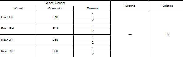
Is the inspection result normal? YES >> GO TO 6.
NO >> Repair the circuit.
6.CHECK WIRING HARNESS FOR SHORT TO GROUND
- Turn ignition switch OFF.
- Check continuity between wheel sensor harness connector terminals of suspect wheel and ground.
Is the inspection result normal? YES >> GO TO 7.
NO >> Repair the circuit.
7.CHECK WIRING HARNESS FOR SHORT BETWEEN CIRCUITS
Check continuity between wheel sensor harness connector terminals of suspect wheel.
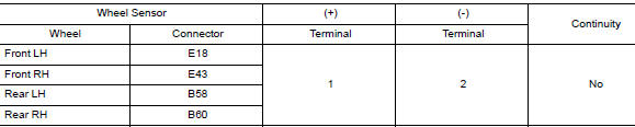
Is the inspection result normal? YES >> GO TO 8.
NO >> Repair the circuit.
8.CHECK WIRING HARNESS FOR OPEN CIRCUIT
Check continuity between ABS actuator and electric unit (control unit) harness connector E125 and harness connector of suspect wheel sensor.
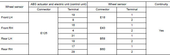
Is the inspection result normal? YES >> GO TO 9.
NO >> Repair the circuit.
9.CHECK ABS ACTUATOR AND ELECTRIC UNIT (CONTROL UNIT) POWER SUPPLY CIRCUIT
- Turn ignition switch ON.
- Check voltage between ABS actuator and electric unit (control unit) harness connector E125 terminal and ground.
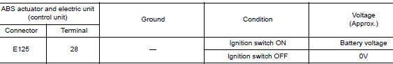
Is the inspection result normal? YES >> GO TO 10.
NO >> Check the following:
- 10A fuse No. 21 located in the FUSE BLOCK (J/B)
- Harness between ABS actuator and electric unit (control unit) and IPDM E/R
10.CHECK ABS ACTUATOR AND ELECTRIC UNIT (CONTROL UNIT) GROUND CIRCUIT
- Turn ignition switch OFF.
- Check continuity between ABS actuator and electric unit (control unit) connector E125 terminals and ground.
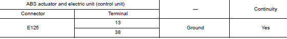
Is the inspection result normal? YES >> GO TO 11.
NO >> Repair or replace malfunctioning components.
11.CHECK WHEEL SENSOR INPUT VOLTAGE
- Connect ABS actuator and electric unit (control unit) connector E125.
- Turn ignition switch ON.
- Check voltage between suspect wheel sensor harness connector terminals.
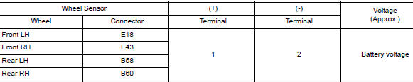
Is the inspection result normal? YES >> Replace wheel sensor. Refer to BRC-132, "FRONT WHEEL SENSOR : Removal and Installation" or BRC-134, "REAR WHEEL SENSOR : Removal and Installation". Then, GO TO 12.
NO >> Replace ABS actuator and electric unit (control unit). Refer to BRC-136, "Removal and Installation".
12.CONFIRM REPAIR
 With CONSULT
- Clear all DTCs.
- Perform DTC confirmation procedure. Refer to BRC-74, "DTC Logic".
Does DTC C1105, C1106, C1107 or C1108 reset? YES >> Replace ABS actuator and electric unit (control unit). Refer to BRC-136, "Removal and Installation".
NO >> Inspection End.

 C1105, C1106, C1107, C1108 wheel sensor
DTC Logic
DTC DETECTION LOGIC
DTC
Display Item
Malfunction detected condition
Possible causes
C1105
RR RH SENSOR-2
When distance between rear ...
Other materials:
Diagnosis system (TCM)
DIAGNOSIS DESCRIPTION
DIAGNOSIS DESCRIPTION : 1 Trip Detection Diagnosis and 2 Trip Detection
Diagnosis
NOTE:
“Start the engine and turn OFF the ignition switch after warm-up.” This is
defined as 1 trip.
1 TRIP DETECTION DIAGNOSIS
When initial malfunction is detected, TCM memorizes DTC. ...
Vehicle loading information
WARNING
It is extremely dangerous to ride
in a cargo area inside a vehicle. In
a collision, people riding in these
areas are more likely to be seriously
injured or killed.
Do not allow people to ride in any
area of your vehicle that is not
equipped ...
Precaution
Precaution for Supplemental Restraint System (SRS) "AIR BAG" and "SEAT
BELT
PRE-TENSIONER"
The Supplemental Restraint System such as “AIR BAG” and “SEAT BELT PRE-TENSIONER”,
used along
with a front seat belt, helps to reduce the risk or severity of injury to the
...
